background image

Page 6 of 52 


Removing the battery 

Required work steps: 


None


Required tools: 


none 


► 

Close the display. 

► 

Disconnect the mains plug from the mains outlet. 

► 

Disconnect all the cables that are connected to the notebook. 

► 

Turn your notebook over and place it on a stable and flat surface. If necessary, place a non-slip cloth on the surface to avoid 
scratching the notebook. 


► 

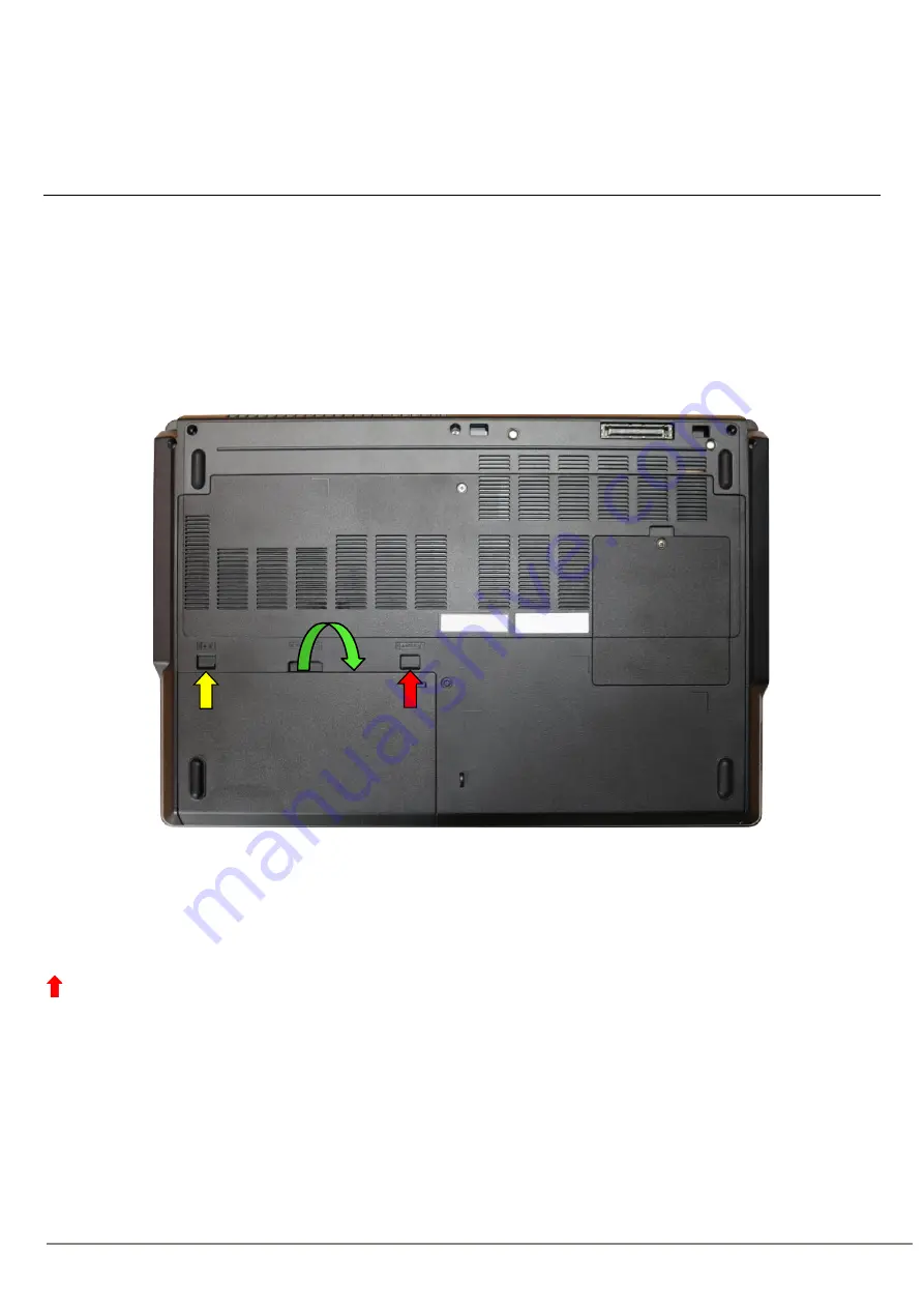
Slide the connector lock in the yellow arrow direction. 

► 

Slide the connector lock in the red arrow direction and hold it in place. 

► 

Lift the battery and remove it (green arrow). 


  Return to Table of Contents 


Содержание CELSIUS H7510

Страница 1: ...oard 21 Removing the memories under the keyboard 23 Removing the M 2 module under the keyboard 24 Removing the lower assy 25 Removing the SmartCard sub board 26 Removing the TPM module Nation Z 27 Removing the touchpad buttons sub board 28 Removing the palm vein fingerprint sensor sub board 29 Removing the DC in connector 31 Removing the mainboard 33 Removing the USB audio sub board 34 Removing th...

Страница 2: ...before opening the device After unplugging the mains plug discharge the remaining voltage by pressing the activation button Remove all externally connected cables Take care not to pinch any cables when installing removing components Please ensure that the installed components that might heat up intensely during operation do not exceed the permitted operating temperature Please take note of the tar...

Страница 3: ... use items with sharp edges screwdrivers to lever them out Parts with Electrostatic Sensitive Devices ESD can be identified by a corresponding label When dealing with boards with ESDs the following points must always be observed Always ensure there is a static discharge e g by touching a grounded object prior to commencing with the work The devices and tools being used must not be statically charg...

Страница 4: ...Page 4 of 52 Screws Screw M2XL4 Screwdriver Phillips PH00 Screw M2 5XL6 D4 5 Screwdriver Phillips PH00 Screw M2XL2 5 Screwdriver Phillips PH00 Return to Table of Contents ...

Страница 5: ...Page 5 of 52 Tools Screwdriver Phillips PH00 Plastic tool Plastic tool Return to Table of Contents ...

Страница 6: ...are connected to the notebook Turn your notebook over and place it on a stable and flat surface If necessary place a non slip cloth on the surface to avoid scratching the notebook Slide the connector lock in the yellow arrow direction Slide the connector lock in the red arrow direction and hold it in place Lift the battery and remove it green arrow Return to Table of Contents ...

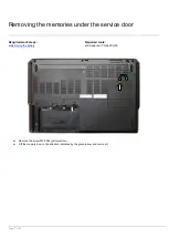
Страница 7: ...mories under the service door Required work steps Removing the battery Required tools Screwdriver Phillips PH00 Remove the screw M2 5XL6 yellow arrow Lift the memory door in the direction indicated by the green arrow and remove it ...

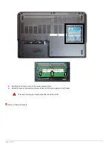
Страница 8: ...Page 8 of 52 Release the locks and push them sideways yellow arrows Remove the memory in the direction indicated by the arrow green arrows Return to Table of Contents ...

Страница 9: ...e service door Required work steps Removing the battery Required tools Screwdriver Phillips PH00 Remove the screw M2 5XL6 yellow arrow Lift the memory door in the direction indicated by the green arrow and remove it Note the coding of the memory ...

Страница 10: ...efully place the memory into the socket green arrow Carefully press on the memory yellow arrows until the lock engages on both sides The same memory type must be inserted into all four slots Return to Table of Contents ...

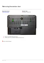
Страница 11: ...ervice door Required work steps Removing the battery Required tools Screwdriver Phillips PH00 Remove the screw M2 5XL6 yellow circles Lift the service door in the direction indicated by the green arrows Return to Table of Contents ...

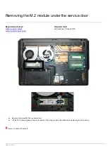
Страница 12: ... work steps Removing the battery Removing the service door Required tools Screwdriver Phillips PH00 Remove the screw M2XL3 yellow arrow Lift the M 2 module green arrow and remove it from the socket in the direction indicated by the blue arrow Return to Table of Contents ...

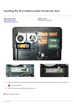
Страница 13: ...ttery Removing the service door Required tools Screwdriver Phillips PH00 Insert the M 2 module into the socket in the direction indicated by the yellow arrow and carefully press it on the other side Observe the coding Fix the M 2 module with an M2XL3 screw yellow circle Return to Table of Contents ...

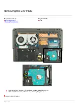
Страница 14: ...steps Removing the battery Removing the service door Required tools none Open the connector lock green arrow upwards and remove the flexprint cable Lift the HDD from the casing in the direction indicated by the yellow arrow Return to Table of Contents ...

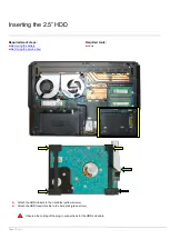
Страница 15: ...teps Removing the battery Removing the service door Required tools none Attach the HDD rubbers to the hard disk yellow arrows Attach the HDD flexprint cable to the hard disk green arrow Observe the coding of the plug in connections for the HDD and cable ...

Страница 16: ...Page 16 of 52 Insert the hard disk Insert the flexprint cable into the intended plug and close the connector lock green arrow Return to Table of Contents ...

Страница 17: ...atory Support Bulletins for Disassembly SB M 10030 Minimum requirements to properly finalise hardware repairs on mobile systems SB M 15007 WIN8x WIN10 Spare product key for repaired devices For any information about ESD please refer to the web based training course ESD in electronics ...

Страница 18: ...uired work steps Removing the battery Removing the service door Required tools Screwdriver Phillips PH00 Remove both LTE antennas yellow arrows Remove the screw M2XL3 yellow circle Remove the LTE module from the socket in the direction indicated by the green arrow Return to Table of Contents ...

Страница 19: ...red work steps Removing the battery Removing the service door Required tools Screwdriver Phillips PH00 Remove the two WLAN antennas yellow circle Remove the screw M2XL3 yellow arrow Remove the WLAN module from the socket in the direction indicated by the green arrow Return to Table of Contents ...

Страница 20: ...y Removing the service door Required tools Screwdriver Phillips PH00 Remove the three screws M2 5XL6 yellow circles Remove the fan cable yellow arrows from the mainboard Remove the cable from the mainboard blue arrow and disconnect it Remove the fan on the right first then the one on the left Return to Table of Contents ...

Страница 21: ...ce door Removing the fan Required tools Screwdriver Phillips PH00 Plastic tool Remove the four M2 5XL6 screws yellow circles Place the opened notebook on its side and carefully press on the openings against the underside of the keyboard to release the keyboard from the casing Hold the keyboard with your other hand to prevent it from falling out ...

Страница 22: ... service technicians Carefully remove the keyboard green arrows and slide it upwards in order to reach the flexprint cable Open the connector lock green arrow upwards to remove the keyboard cable Remove the keyboard Return to Table of Contents ...

Страница 23: ...the keyboard Required work steps Removing the battery Removing the service door Removing the fan Removing the keyboard Required tools none Release the locks and push them sideways yellow arrows Remove the memory in the direction indicated by the arrow green arrows Return to Table of Contents ...

Страница 24: ...he keyboard Required work steps Removing the battery Removing the service door Removing the fan Removing the keyboard Required tools Screwdriver Phillips PH00 Remove the screw M2XL3 yellow arrow Lift the M 2 module green arrow and remove it from the socket blue arrow Return to Table of Contents ...

Страница 25: ...door Removing the 2 5 HDD Removing the LTE module Removing the WLAN module Required tools Screwdriver Phillips PH00 Plastic tool Remove the 15 screws M2 5XL6 yellow circles Disconnect the WLAN and LTE antennae yellow arrows Carefully loosen the lower assy from the upper assy with the plastic tool and remove the lower assy Return to Table of Contents ...

Страница 26: ...e service door Removing the 2 5 HDD Removing the LTE module Removing the WLAN module Removing the lower assy Required tools none Open the connector lock green arrow upwards and remove the flexprint cable Carefully press the plastic latch in the direction indicated by the yellow arrow and remove the sub board orange arrow Return to Table of Contents ...

Страница 27: ... battery Removing the service door Removing the 2 5 HDD Removing the LTE module Removing the WLAN module Removing the lower assy Required tools none The standard TPM module yellow frame is permanently soldered to the mainboard The TPM module Nation Z blue frame is optional and placed on the mainboard Return to Table of Contents ...

Страница 28: ...y Removing the service door Removing the 2 5 HDD Removing the LTE module Removing the WLAN module Removing the lower assy Required tools Screwdriver Phillips PH00 Remove both screws M2 5XL6 yellow circles Open all connector locks green arrows upwards and remove the flexprint cables Remove the sub board orange arrow Return to Table of Contents ...

Страница 29: ...oard Required work steps Removing the battery Removing the service door Removing the 2 5 HDD Removing the LTE module Removing the WLAN module Removing the lower assy Required tools Screwdriver Phillips PH00 Remove the screws M2 5XL6 yellow circle Remove the bracket in the direction indicated by the yellow arrow ...

Страница 30: ...e connector lock green arrow upwards and remove the flexprint cable Remove the sub board blue arrow The frame in which the sub board is located has been adjusted for the respective sensor Frame for fingerprint sensor Frame for palm vein sensor Return to Table of Contents ...

Страница 31: ... connector Required work steps Removing the battery Removing the service door Removing the 2 5 HDD Removing the LTE module Removing the WLAN module Removing the lower assy Required tools Screwdriver Phillips PH00 Remove the M2 5XL6 screws yellow arrow and remove the door green arrow ...

Страница 32: ...Page 32 of 52 Only intended for authorised service technicians Remove the plug from the mainboard yellow arrow and remove the cable Return to Table of Contents ...

Страница 33: ... Removing the fan Removing the mains connection Required tools Screwdriver Phillips PH00 Remove both screws M2 5XL6 yellow arrows Open the display cable connector lock orange arrow and disconnect the cable from the bracket blue arrows Open the four connector locks green arrows upwards and remove the flexprint cables Carefully tilt the mainboard away from you so that you can reach the sub board bel...

Страница 34: ...B audio sub board Required work steps Removing the battery Removing the service door Removing the fan Removing the keyboard Removing the M 2 module under the keyboard Removing the 2 5 HDD Removing the LTE module Removing the WLAN module Removing the lower assy Required tools none ...

Страница 35: ...e connector lock green arrow upwards and remove the flexprint cable Remove the speaker cable blue arrow from the sub board Carefully press the plastic latches in the direction indicated by the yellow arrow and remove the sub board orange arrow Return to Table of Contents ...

Страница 36: ...k steps Removing the battery Removing the service door Removing the fan Removing the 2 5 HDD Removing the LTE module Removing the WLAN module Removing the lower assy Removing the M 2 module under the service door Removing the mains connection Removing the mainboard Required tools Screwdriver Phillips PH00 ...

Страница 37: ...nded for authorised service technicians Remove the screw M2XL4 yellow circle Carefully press the plastic latches in the direction indicated by the yellow arrow and remove the sub board green arrow Return to Table of Contents ...

Страница 38: ...moving the 2 5 HDD Removing the LTE module Removing the WLAN module Removing the lower assy Removing the M 2 module under the service door Removing the mains connection Removing the mainboard Removing the USB audio sub board Required tools Screwdriver Phillips PH00 Disconnect the WLAN and LTE antennae yellow arrows Remove the screw M2 5XL6 yellow circle Turn the upper assy by 90 green arrows and r...

Страница 39: ... the keyboard Removing the M 2 module under the keyboard Removing the 2 5 HDD Removing the LTE module Removing the WLAN module Removing the lower assy Removing the M 2 module under the service door Removing the mains connection Removing the mainboard Removing the USB audio sub board Removing the display Required tools Plastic tool Start in the top left by opening the display yellow arrow ...

Страница 40: ...nicians Use the plastic tool to open the display frame Carefully use a plastic tool to loosen the plastic latches in the direction indicated by the yellow arrows to disconnect the LCD back cover assy from the LCD front cover assy Return to Table of Contents ...

Страница 41: ... the keyboard Removing the 2 5 HDD Removing the LTE module Removing the WLAN module Removing the lower assy Removing the M 2 module under the service door Removing the mains connection cable Removing the mainboard Removing the USB audio sub board Removing the display Removing the LCD front cover assy Required tools Screwdriver Phillips PH00 Remove the four M2XL2 5 screws yellow circles and flip th...

Страница 42: ...of 52 Only intended for authorised service technicians Remove both adhesive tapes metal and transparent and remove the plug from the LCD panel in the direction indicated by the arrow Return to Table of Contents ...

Страница 43: ... keyboard Removing the 2 5 HDD Removing the LTE module Removing the WLAN module Removing the lower assy Removing the M 2 module under the service door Removing the mains connection Removing the mainboard Removing the USB audio sub board Removing the display Removing the LCD front cover assy Required tools Screwdriver Phillips PH00 Remove the six M2 5XL3 screws yellow circles and remove the hinges ...

Страница 44: ...the keyboard Removing the M 2 module under the service door Removing the 2 5 HDD Removing the LTE module Removing the WLAN module Removing the lower assy Removing the M 2 module under the keyboard Removing the mains connection Removing the mainboard Removing the USB audio sub board Removing the display Removing the LCD front cover assy Required tools Screwdriver Phillips PH00 ...

Страница 45: ...y intended for authorised service technicians Remove the plug yellow arrow from the webcam Attach the plastic tool as shown and detach the webcam carefully Caution It is attached very firmly Return to Table of Contents ...

Страница 46: ...s storage HDD SSD depending on the device configuration x x 8 Fan x 50 58 Mainboard depending on the device configuration x x x 161 WLAN module depending on the device configuration x 162 LTE module depending on the device configuration x 64 TPM module x 150 LCD panel depending on the device configuration x x 130 Keyboard depending on the device configuration x x 163 164 Fingerprint palmvein sub b...

Страница 47: ...Page 47 of 52 ...

Страница 48: ...Page 48 of 52 ...

Страница 49: ...Page 49 of 52 ...

Страница 50: ...Page 50 of 52 ...

Страница 51: ...ed flame retardants but to the best of our know ledge w e provide this information to sort them out Plastic parts location can be visually identified by their typical design function for the product also show n in the disassembly manual Many of these parts Greater than 25 grams are bromine free Regardless these parts are labeled usually molded directly into the plastic per ISO 11469 A typical labe...

Страница 52: ...Page 52 of 52 ...

Отзывы: