background image

U41119-J-Z126-1-74

 29

Operating the drives

Operating the streamer drive (optional)

5.3 Operating the streamer drive (optional)

Please also observe the instructions later in this section for handling magnetic tape 
cartridges.

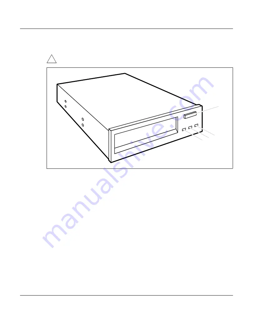
Figure 17: Control panel of the streamer drive

1 = Remove button

3 = “Activity” indicator

2 = “Ready” indicator

4 = “Fault” indicator

When the system unit is powered up, the streamer performs a self-test, during which time 
the indicators are also lit or flashing. The meaning of the indicators during normal operation 
is as follows: 

The “Ready” indicator (2)

is dark when there is no tape cartridge loaded,

is lit green when there is a tape cartridge loaded and the drive is ready.

The “Activity” indicator (3)

is dark when the drive is not active,

flashes green when the tape is in motion, when a tape cartridge is currently being 
ejected, or when a cleaning operation is being performed.

The “Fault” indicator (4)

is dark when no fault condition exists,

is lit amber when a cleaning operation is required or currently being performed,

flashes if a drive fault or a tape cartridge fault has occurred.

!

1

2

3

4

Содержание SKP 3970-2 Series

Страница 1: ...ocessor it supports the operation monitoring troubleshooting and maintenance of the business server as well as TELESERVICE Figure 1 3970 20 tower left and 3970 29 rack module right The 3970 2x Service Console Processor is available in the following housing variants tower 3970 20 SKP rack module 3970 29 SKP The SKP variants are supplemented by color monitor 3970L 30 31 40 keyboard 3970L 10 mouse 39...

Страница 2: ...dition system specific logging is supported with the option of setting the archiving strategy size and number of logging files separately for each system The VMOP function diskettes also allow system specific support through the 3925 ATOP A streamer can optionally be incorporated in the 3970 2x Service Console Processor This can be used to back up the logging files of the programs KVP TSB2000 and ...

Страница 3: ...ularly important for the functioning of the product This symbol identifies important notes e g warnings Following this symbol you will find a reference to the SINIX 2000 V7 5 V8 0 User Guide 1 Ê This symbol identifies actions to be performed e g required keyboard inputs Literature reference or optional parameters in commands This typewriter typeface is used for names commands and messages e g the ...

Страница 4: ...Eine Dokuschablone von Frank Flachenecker by f f 1992 ...

Страница 5: ... as the following safety instructions The ON OFF switch does not disconnect the 3970 2x SKP from the mains voltage The CD ROM drive contains a light emitting diode LED classification as per IEC 825 1 1993 LASER CLASS 1 and should not therefore be opened 2 2 Observed standards 2 2 1 Radiation and resistance This equipment satisfies the requirements of EU Directive 89 336 EEC Electromagnetic Compati...

Страница 6: ...P Important information 2 2 3 RFI suppression FCC Part 15 Subpart J Class B 2 3 Door of the 3970 2x SKP Do not open the door of the 3970 2x SKP except to perform operator actions After performing any such actions close the door again and lock it ...

Страница 7: ...ter entitled Important information 3 1 Installing the operating system For a description of how to install the SINIX 2000 Z V7 5 operating system refer to the section entitled Installing SINIX 2000 in the chapter Installing SINIX 2000 V7 5 of the SINIX 2000 V7 5 V8 0 User Guide 1 V8 ...

Страница 8: ...ock The door remains closed Ê If you only want to access the ON OFF switch and the available drives grip the drive cover by the handle and pull it first towards you 2a and then in a downward direction 2b You can leave the key in the lock Ê If you need to access the drive modules of the server you have to open the door 3 1 3 2 b 2 a 2 ...

Страница 9: ... the drive cover but keep the door locked This is done as follows Ê Open the lock Figure 3 Opening the drive cover on the tower Ê Take the handle at the bottom of the drive cover and pull it towards you 1 Ê Reinstate the lock 2 Ê Push the drive cover in a downward direction 3 1 2 3 ...

Страница 10: ... the tower not supported 1 2 7 4 8 6 5 3 1 Display CD ROM drive active not active 2 Display SCSI bus active not active 3 Status indicator 4 ON OFF switch 5 Display chipcard reader active not active 6 Display floppy disk drive active not active 7 Display hard disk drive active not active 8 Display hard disk error ...

Страница 11: ...e not supported 8 7 6 5 3 2 4 1 1 Display CD ROM drive active not active 2 Display SCSI bus active not active 3 Status switch 4 ON OFF switch 5 Display chipcard reader active not active 6 Display floppy disk drive active not active 7 Display hard disk drive active not active 8 Display hard disk error ...

Страница 12: ...nd off If it has been switched off the green status indicator is lit 3 The ON OFF switch does not disconnect the 3970 2x SKP from the mains voltage To completely disconnect it from the mains voltage the mains plug on the 3970 2x SKP must be pulled out 5 Chipcard reader display The chipcard reader is not supported 6 Display floppy disk drive active not active This indicator is lit when the floppy d...

Страница 13: ... 3970 2x SKP performs a self test If once the 3970 2x SKP has been switched on only flickering stripes appear on the screen switch the monitor off and notify the Customer Service Department The 3970 2x SKP is ready for operation if the SINIX welcome window appears on the screen If this window does not appear something has gone wrong when powering up the SKP Restart the powering up procedure If thi...

Страница 14: ...ctivate the SINIX screen Ê Enter the following command init 0 or press the ON OFF pushbutton The operating system is then powered down in the proper manner and the 3970 2x SKP is deactivated The green status indicator 2 is extinguished The ON OFF switch does not disconnect the 3970 2x SKP from the mains voltage To completely disconnect it from the mains voltage the mains plug on the 3970 2x SKP mu...

Страница 15: ...U41119 J Z126 1 74 15 Operation Locking the tower 3 5 Locking the tower Figure 7 Locking the tower Ê Close the drive cover 1 and or the door of the server 2 Ê Turn the key counterclockwise 3 3 1 2 2 ...

Страница 16: ...on 3 6 Service tray in the tower Figure 8 Service tray in the tower CDs floppy disks and administrator and maintenance information e g maintenance stickers SKP network address can be kept in a secure and handy location in the tray on the front of the server ...

Страница 17: ...ontain plastic solvents when cleaning the 3970 2x SKP Take care that no liquids get into the interior of the equipment Make sure that the ventilation slots on the 3970 2x SKP and on the monitor remain unobstructed The surface of the 3970 2x SKP and of the monitor may also be cleaned using a dry cloth If the surface is particularly dirty a damp cloth that has been moistened in water containing a mi...

Страница 18: ...Eine Dokuschablone von Frank Flachenecker by f f 1992 ...

Страница 19: ...U41119 J Z126 1 74 19 4 Rack Observe the safety instructions given in the chapter entitled Important information Figure 9 Front view of the rack ...

Страница 20: ... Unlocking the rack Ê Turn the key clockwise 1 Ê The handle swings out to the front 2 Ê Turn the handle counterclockwise through approx 90 degrees 3 Locking Ê Push the keyboard tray in Ê Close the door Ê Turn the handle clockwise until it is in an upright position Ê Press the handle in as far as it will go 3 1 2 ...

Страница 21: ...ntain plastic solvents when cleaning Take care that no liquids get into the interior of the equipment Make sure that the ventilation slots on the SKP remain unobstructed The surface of the rack may also be cleaned using a dry cloth If the surface is particularly dirty a damp cloth that has been moistened in water containing a mild cleaning agent and well wrung out should be used Use an established...

Страница 22: ...Eine Dokuschablone von Frank Flachenecker by f f 1992 ...

Страница 23: ...destroy the read write heads in the floppy disk drive within a mere 20 seconds Figure 11 Inserting a floppy disk 1 Insertion direction 5 Eject button for inserted floppy disks 2 Label field 6 Floppy disk is write protected 3 Write protect slider 7 Floppy disk is not write protected 4 ID for a 1 44 Mb floppy disk Inserting a floppy disk Ê Insert the disk into the floppy disk drive in the direction ...

Страница 24: ... allows you to protect the data on the floppy disk from being accidentally overwritten or deleted Protecting a floppy disk against overwriting Ê Push the write protect slider to position 6 The write protect slider reveals the opening Removing write protection Ê Push the write protect slider to position 7 The write protect slider covers the opening i ...

Страница 25: ... 4 Button for manual removal 2 Headphone volume control 5 Insert Remove button 3 Status indicator 6 CD drawer Status indicator The status indicator 3 flashes when a CD is being inserted It goes dark when the drive is ready to read If the status indicator does not go dark after a CD has been inserted but continues to flash the CD may well be damaged or dirty The status indicator is permanently lit ...

Страница 26: ...CD ROM drive Operating the drives Inserting a CD Ê Press the Insert Remove button 1 Figure 13 Opening the CD ROM drawer The CD drawer opens Ê Insert the CD with the label side facing up into the CD drawer Figure 14 Inserting the CD ROM 1 ...

Страница 27: ...e is being accessed Wait until the status indicator goes dark before pressing the Insert Remove button Ê Press the Insert Remove button The CD drawer opens Ê Remove the CD from the CD drawer Ê Press the Insert Remove button or press gently against the CD drawer The CD drawer closes If the CD drawer does not open check whether the CD ROM drive has been locked by means of a software command If this ...

Страница 28: ...ngerprints Never touch the surface of a CD Always keep CDs in their sleeves or cases In this way you will prevent them from becoming dusty scratched or otherwise damaged Protect CDs from contamination and do not leave them in a position where they are exposed to direct sunlight Store CDs horizontally Avoid storing CDs in places that are excessively warm or humid Protect the CD ROM drive from stron...

Страница 29: ... also lit or flashing The meaning of the indicators during normal operation is as follows The Ready indicator 2 is dark when there is no tape cartridge loaded is lit green when there is a tape cartridge loaded and the drive is ready The Activity indicator 3 is dark when the drive is not active flashes green when the tape is in motion when a tape cartridge is currently being ejected or when a clean...

Страница 30: ... drive and do not power the 3970 2x SKP down while a cartridge is being read or written to Always leave the touch guard in place over the opening for the read write head Never touch the magnetic tape The conditions for the storage of cartridges should be similar to the conditions appli cable to operation Store cartridges on edge wherever possible Inserting a magnetic tape cartridge Take care when ...

Страница 31: ...sing the write protection facility If you wish to protect a magnetic tape cartridge against being accidentally overwritten or deleted you can activate the write protection facility When write protection has been activated for a magnetic tape cartridge the system can only read the data on the cartridge but cannot overwrite or delete it Figure 18 Write protection for the magnetic tape cartridge On t...

Страница 32: ...d Use a cleaning set consisting of a cleaning cartridge sponges cleaning fluid and plastic tweezers The interval between cleaning operations depends primarily on how often the streamer is used Observe the following general rules Even if you use the streamer less frequently than indicated above the read write heads should be cleaned at least once every three months Period of operation Cleaning Cont...

Страница 33: ...own Fault in the power supply module The status indicator for the defective power supply module is not lit The PDA management facility has detected a fault Ê Contact our Customer Service Department Screen remains dark If the screen remains dark this may have the following causes Monitor is switched off Ê Switch the monitor on Screen is blanked Ê Press any key on the keyboard Brightness control is ...

Страница 34: ...e and date incorrect The changeover to summer time is handled automatically by the SINIX 2000 operating system Ê You can set winter time and or the date in the operating system under SYSADM system administration in the System Configuration menu For further details refer to the section on setting the system time in the chapter on system administration in SINIX in the SINIX 2000 V7 5 V8 0 User Guide...

Страница 35: ...standing tradition we have been reclaiming and recycling decommissioned computer systems for over a decade As early as the design stage we place particular emphasis on the reusability of materials For example all of the larger computer parts that are made of synthetic materials are clearly marked to indicate their constituents in order to simplify subsequent recycling processes Wherever possible y...

Страница 36: ...Eine Dokuschablone von Frank Flachenecker by f f 1992 ...

Страница 37: ...numbers Germany Siemens IT Service GmbH Co Call Management Center CMC Telephone nationwide 0180 54040 Fax nationwide 0180 533 6 779 International Please contact your local dealer or Siemens office to find out the telephone and fax numbers for your area ...

Страница 38: ...Eine Dokuschablone von Frank Flachenecker by f f 1992 ...

Страница 39: ...s service con sole processor 3970 2x channel adapters 3970 and 3971 business server SR2000 B and enterprise data server DS2000 are ready for use This includes helpful information on con figuring the systems and a description of important functions for system operation and administration Order number U24789 J Z385 3 2 S115 Business Server Operating Manual Target group This manual is intended for op...

Страница 40: ...intended for operators and system administrators working with the S150 Business Server Contents The manual describes the hardware specific operating functions of the S150 Business Ser ver It presents the SVP frames and describes the standard tasks for operators using these frames Order number U41018 J Z126 1 76 5 S160 Business Server Operating Manual Target group This manual is intended for operat...

Страница 41: ...5 drive cover 9 E error message 34 I indicators 10 L lock rack 20 N notational conventions 3 O operating system 7 R rack clean 21 lock 20 unlock 20 rack module 3970 20 SKP 1 recycling 35 RFI suppression 6 S safety information 5 service telephone 37 service console processor SKP 1 SKP Service Console Processor 1 status indicator 33 summer time 34 T time 34 tower unlock 8 U unlock rack 20 tower 8 W ...

Страница 42: ......

Страница 43: ...ling the operating system 7 3 2 Unlocking the tower 8 3 3 Controls and indicators 10 3 4 Switching the 3970 2x SKP on and off 13 3 5 Locking the tower 15 3 6 Service tray in the tower 16 3 7 Cleaning the 3970 2x SKP 17 4 Rack 19 4 1 Unlocking and locking the rack 20 4 2 Cleaning the rack 21 5 Operating the drives 23 5 1 Operating the floppy disk drive 23 5 2 Operating the CD ROM drive 25 5 3 Opera...

Страница 44: ...U41119 J Z126 1 74 Contents Related publications 39 Index 41 ...

Страница 45: ...ble to operate the hardware of the 3970 2X Service Console Processor Edition November 1999 File skp2 pdf Copyright Fujitsu Siemens Computers GmbH 1999 All rights reserved Delivery subject to availability right of technical modifications reserved All hardware and software names used are trademarks of their respective manufacturers This manual was produced by cognitas Gesellschaft für Technik Dokume...

Страница 46: ...e Processor U41119 J Z126 1 74 Fujitsu Siemens computers GmbH User Documentation 81730 Munich Germany Fax 089 636 40443 Internet manuals fujitsu siemens com http manuals fujitsu siemens com Comments Suggestions Corrections Submitted by ...

Страница 47: ...tsu com Copyright Fujitsu Technology Solutions 2009 Hinweise zum vorliegenden Dokument Zum 1 April 2009 ist Fujitsu Siemens Computers in den alleinigen Besitz von Fujitsu übergegangen Diese neue Tochtergesellschaft von Fujitsu trägt seit dem den Namen Fujitsu Technology Solutions Das vorliegende Dokument aus dem Dokumentenarchiv bezieht sich auf eine bereits vor längerer Zeit freigegebene oder nic...

Отзывы: