FinePix S5800/S800 Service Manual
3-3
3. Schematics
Confidential: FUJIFILM Service Center Use Only
3-2-2.
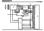
Outline of Operation
When the shutter is released, a reset signal and serial
signal (TAKE A PICTURE instruction) are sent from the 8-bit
microprocessor as input for the ASIC and CPU and operation
begins. When the TG/SG drives the CCD, the image data
passes through A/D conversion and the CDS and is input to
the ASIC as 12-bit data. The input data then passes through
the digital clamp and is input to the SDRAM.
This data is then used to calculate the AF, AE, AWB,
shutter and AGC values. Exposure is normally carried
out 3 more times to obtain the best possible image. The
image data temporarily held in SDRAM is then loaded into
the CPU and the colors are generated. The RGB data for
each pixel is obtained by interpolating from the RGB data
for the surrounding pixels. Following AWB and gamma
(γ) processing, the matrix is obtained and the aperture is
corrected for the Y signal. This data is then compressed in
JPEG format and written to card memory (xD-Picture card or
SD card). When the data is output to external media, the data
is taken from memory and output as serial data via USART.
When images are displayed on the LCD or monitor, the data
is transferred from memory to SDRAM, expanded into the
SDRAM display area and then displayed.
3-2-3.
LCD Block
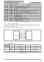
The LCD display circuit is on the CP1 board and includes its
own power supply circuit.
The signals from the ASIC are 8-bit digital signals and are
input directly to the LCD. In the LCD, they are converted to
RGB signals by the driver circuit. The LCD controls factors
such as brightness and image quality using a 3-wire serial
interface.
Because the LCD elements close in response to differences
in potential between the VCOM (common electrode voltage:
AC) and RGB, the larger the difference, the darker the
display. Conversely, a smaller potential difference opens
the elements and brightens the display. In addition to video
signals, timing pulses are also input directly to the LCD from
the ASIC.
3-2-4.
EVF Block
The EVF display circuit is on the CP1 board and includes
its own power supply circuit. The signals from the ASIC
consist of 8-bit digital signals, serial control signals and
synchronization control signals, and are input to the EVF
driver IC. In the driver IC, the 8-bit digital signals are
converted to RGB signals. The serial control signals are used
to control factors such as the image quality.
3-2-5.
Lens Drive Block
Focus drive
The 16-bit serial data signals (LENS_SD, LENS_CK and
LENS_EN) output from the ASIC (IC101) are driven (FOCUS
A+, FOCUS A-, FOCUS B+ and FOCUS B-) by the motor
driver IC (IC951) and in turn drive the stepping motor used
for focusing in microstep increments. The focus reference
position is detected by a photo-interrupter (F_SENSE) in the
lens block.
Zoom drive
The 16-bit serial data signals (LENS_SD, LENS_CK and
LENS_EN) output from the ASIC (IC101) are driven (ZOOM
A+, ZOOM A-, ZOOM B+ and ZOOM B-) by the motor
driver IC (IC951) and in turn drive the stepping motor used
for zooming in microstep increments. The zoom reference
position is detected by a photo-interrupter (Z_SENSE) in the
lens block.
ND filter
The ND filter drive signals (NDON and NDOFF) output from
the ASIC (IC101) are driven using a fixed current (ND+, ND-)
and are inserted into or withdrawn from the ND filter light
path by the motor driver (IC951).
Aperture drive
A damped, coil-less galvanometer drive is used for the
aperture.
The hole sensor output in the lens is amplified by the hold-
amplifier circuit in the lens drive IC (IC971) and the difference
between that output and the target aperture value as
determined from the exposure amount output from the ASIC
(IC101) is input to the servo-amp circuit (in IC971) and is
automatically controlled so that it matches the target aperture
size.
The lens aperture control signal is output by IC971 and input
to IN6B in IC951.
IC951 operates as the driver for the lens drive.
Shutter drive
The shutter is driven by applying reverse voltage to the
aperture drive coil. To drive the shutter, the OC_EN and
OC_CONT signals are both maintained at the High level to
input the Low level to IN6B in IC951. At the same time, the
signal output from the ASIC (IC101) is set to the
High level (input to IN6A in IC951) to operate the shutter.
IC951 operates as the driver for the lens drive.
Содержание FinePix S5800
Страница 6: ...FinePix S5800 S800 Service Manual 6 Confidential FUJIFILM Service Center Use Only MEMO ...
Страница 36: ...FinePix S5800 S800 Service Manual 2 22 2 Disassembly Confidential FUJIFILM Service Center Use Only MEMO ...
Страница 66: ...FinePix S5800 S800 Service Manual 3 30 3 Schematics Confidential FUJIFILM Service Center Use Only MEMO ...
Страница 68: ...FinePix S5800 S800 Service Manual 3 32 3 Schematics Confidential FUJIFILM Service Center Use Only MEMO ...
Страница 92: ...FinePix S5800 S800 Service Manual 4 24 4 Adjustments Confidential FUJIFILM Service Center Use Only MEMO ...
Страница 98: ...FinePix S5800 S800 Service Manual 5 6 5 Inspection Confidential FUJIFILM Service Center Use Only MEMO ...
Страница 104: ...FinePix S5800 S800 Service Manual 6 6 6 Parts List Confidential FUJIFILM Service Center Use Only MEMO ...
Страница 112: ...FinePix S5800 S800 Service Manual 6 14 6 Parts List Confidential FUJIFILM Service Center Use Only MEMO ...
Страница 114: ...Midtown West 7 3 Akasaka 9 chome Minato ku Tokyo 107 0052 Japan ...

