background image

FinePix S5800/S800 Service Manual

6-9

6. Parts List

Confidential: FUJIFILM Service Center Use Only

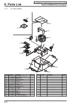
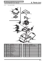
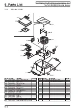
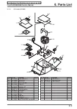
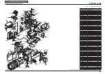
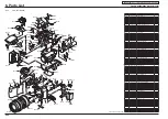
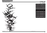
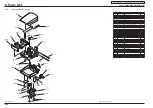
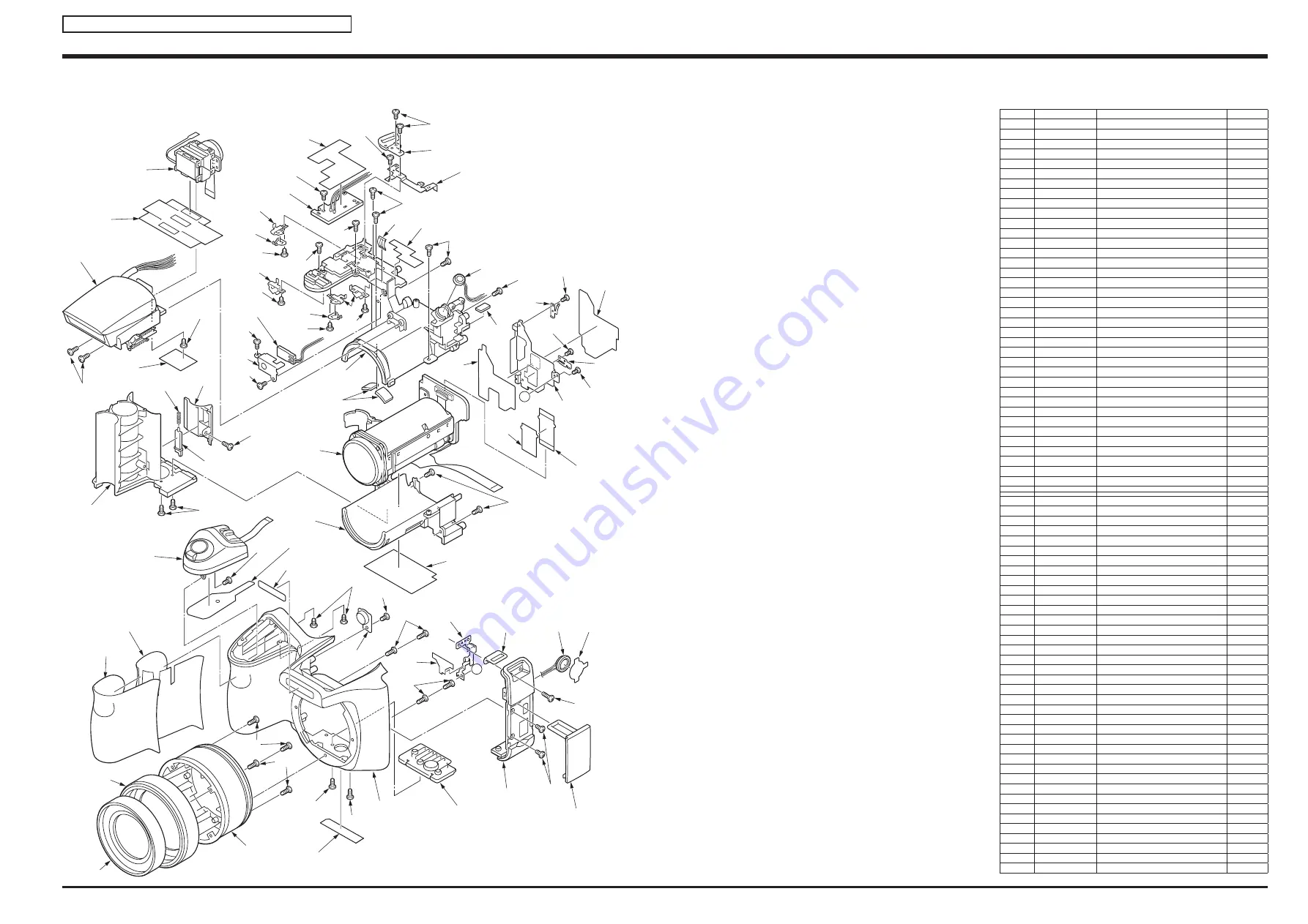
6-3-2. 

EU/EG/EE-model (S5800)

Ref No. Parts No.

Description

Comment

M301

636-102-7458

LENS RING TOP

M302

636-107-0010

LENS RING MIDDLE

M303

636-107-0003

LENS RING BOTTOM BLACK

M304

636-102-7380

FRONT GRIP

M305

636-104-5766

ADHESIVE GRIP FRONT

M306

636-102-9780

ZOOM SW UNIT SHEET

M307

645-092-3760

ZOOM SW UNIT BLACK

M308

636-103-0083

LOGO BADGE BLACK

M309

636-102-7397

AF LED COVER

M310

636-105-5826

FRONT CABINET BLACK

M311

636-102-7465

STAND BLACK

M312

636-102-7434

SIDE CABI

M313

636-102-7533

JACK COVER

M314

636-104-5964

SPEAKER SHEET

M315

645-088-3484

SPEAKER

M316

636-102-7809

STRAP LENS HOLDER

M317

636-105-5741

STRAP EARTH

M318

636-103-5941

SHEET LENS FPC

M319

636-102-7595

LENS HOLDER BOTTOM BLACK

M320

636-108-6691

LENS ASSY

M321

636-105-5796

CA-1 HOLDER SHEET B

M322

636-105-5758

CA-1 HOLDER

M323

636-105-5765

EARTH HOLDER A

M324

636-105-5772

EARTH HOLDER B

M325

636-104-5575

SHIELD TAPE (FPC)

M326

636-105-6434

FLEXIBLE PWB

M327

636-102-7571

BATTERY HOLDER BLACK

M328

636-102-7663

BATT LOCK KNOB BLACK

M329

636-102-9858

BATT KNOB SPRING

M330

636-102-7526

BATT COVER KNOB BLACK

M331

636-103-8904

SHEET EVF B

M332

636-109-5617

FLASH ASSY[S5800B-EE EU EG CH]

M332

ZP01707-100

FLASH ASSY[S5800B-EE EU EG CH]

M333

636-103-8881

SHEET EVF A

M334

645-092-2756

EVF UNIT

M335

636-102-7588

LENS HOLDER TOP BLACK

M336

636-103-5965

LENS SPACER

M337

636-102-7601

AF LED HOLDER

M338

636-105-1781

COMPL PWB TB-1

M339

636-102-7779

BATT TERMINAL A

M340

636-102-7786

BATT TERMINAL B

M341

636-100-1137

BATT COVER TERMINAL

M342

636-105-1774

COMPL PWB PW-1

M343

636-104-5988

SHEET LEAD POWER

M344

636-102-7793

STRAP GRIP HOLDER

M345

636-102-7700

STRAP GRIP EARTH

M346

636-102-7830

AF LED SPRING

M347

636-103-5958

AF LED SHEET

M348

636-104-6909

LCD SPACER B

M349

636-106-7331

STRAP EARTH SHEET

M350

645-079-9600

MICROPHONE

M351

636-105-5802

CA-1 HOLDER SHEET A

M352

636-105-9664

RATING LABEL BLACK WEE

M353

411-192-4408

SCREW 1.7X6.0

M354

411-177-6502

SCREW 1.7X4

M355

411-177-7202

SCREW 1.7X3

M356

411-190-2208

SCREW 1.4X3

M357

411-180-1808

SCREW 1.7X6.0

M358

411-177-8100

SCREW 1.7X2.5

M359

411-192-4200

SCREW 1.7X3.0

M360

411-189-2608

SCREW 1.4X3

M361

411-184-6601

SCREW 1.4X2.5

M362

411-178-9403

SCREW 1.7X4.0

M363

411-193-2106

SCREW 1.7X4.0

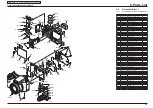
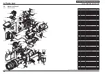
A

A

M301

M302

M303

M304

M305

M306

M307

M308

M309

M310

M311

M312

M313

M314

M315

M316

M317

M318

M319

M320

M321

M322

M323

M324

M325

M326

M327

M328

M329

M330

M331

M332

M333

M334

M335

M336

M337

M338

M339

M339

M341

M342

M343

M344

M345

M346 M347

M348

M349

M350

M351

M352

M353

M354

M354

M354

M354

M354

M354

M354

M355

M355

M355

M355

M356

M356

M357

M357

M357

M357

M358

M358

M358

M358

M358

M359

M360

M360

M359

M361

M363

M341

M340

M354

M363

M363

M362

 Revised: 22, Sep 2008

Содержание FinePix S5800

Страница 1: ...ITICAL FOR SAFETY PLEASE REPLACE ONLY WITH THE COMPONENTS SPECIFIED ON THE SCHEMATIC DIAGRAM AND IN THE PARTS LIST IF YOU USE PARTS NOT SPECIFIED IT MAY RESULT IN A FIRE AND AN ELECTRICAL SHOCK CAUTION BECAUSE THIS PRODUCTIS RoHS LEAD FREE COMPLIANT USE THE DESIGNATED AFTER SELES PARTS AND THE DESIGNATED LEAD FREE SOLDER WHEN PERFORMING REPAIRS Refer to page 3 to page 5 Confidential FUJIFILM Servic...

Страница 2: ...e customer and recommend their replacement 5 Check the B voltage to see it is at the values specified 6 Make leakage current measurements to determine that exposed parts are acceptably insulated from the supply circuit before returning the product to the customer 7 CAUTION FOR CONTINUED PROTECTION AGAINST FIRE HAZARD REPLACE ONLY WITH SAME TYPE 2 5 AMPERES 125V FUSE ATTENTION AFIN D ASSURER UNE PRO...

Страница 3: ...ng When carrying out repairs use a designated lead free solder bearing in mind the differing work practices for conventional solder eutectic and lead free solder Differences in the soldering work for lead free and eutectic solder When the soldering work practices for eutectic solder and lead free solder are compared the main differences are as shown below In particular when lead free solder is use...

Страница 4: ...orrect bonding temperature The correct bonding temperature refers not to the temperature of the heat source but to the bonding temperature that will give the best bond strength Precautions when soldering with lead free solder Soldering iron maintenance Because of the high soldering iron temperature in lead free soldering there is rapid carbonization of the flux adhering to the tip of the soldering ...

Страница 5: ...ead free solders specified below Solder type Sn96 5Ag3Cu0 5 Displayed symbol SnAgCu Wire diameter 0 6 0 8 or 1 0 mm Sample Flux Conventional flux can be used Solder application wires mesh wicking wire etc Conventional application wires can be used lead free Wire diameter 0 8mm Solder type Displayed symbol SnAgCu ...

Страница 6: ...FinePix S5800 S800 Service Manual 6 Confidential FUJIFILM Service Center Use Only MEMO ...

Страница 7: ...s 3 1 3 1 Description of CCD circuit operation 3 1 3 1 1 Overview 3 1 3 1 2 IC931 CCD imager 3 1 3 1 3 IC901 V driver and IC905 H driver 3 2 3 1 4 IC905 CDS AGC and A D converter 3 2 3 2 Description of CP1 circuit operation 3 2 3 2 1 Circuit Description 3 2 3 2 2 Outline of Operation 3 3 3 2 3 LCD Block 3 3 3 2 4 EVF Block 3 3 3 2 5 Lens Drive Block 3 3 3 3 Description of PWA Power Circuit Operati...

Страница 8: ...4 10 AWB Adjustment 4 13 4 11 CCD Defect Detection 4 15 4 12 CCD Black Defect Detection 4 17 4 13 Updating the Firmware 4 19 4 14 Completion Settings 4 22 5 Inspection 5 1 5 1 Required Measuring Equipment 5 1 5 2 Connection of Measuring Equipment 5 1 5 3 Inspection and Factory Settings 5 2 CONTENTS 6 Parts List 6 1 6 1 Packing and Accessories 6 1 6 1 1 US model S800 6 1 6 1 2 EU model S5800 6 2 6 ...

Страница 9: ... approx 1 0 m 3 3 ft to infinity In High speed shooting mode approx 1 0 m 3 3 ft to infinity Macro Wide angle 4 cm to 3 0 m 1 6 in to 9 8 ft Telephoto 60 cm to 3 0 m 2 0 ft to 9 8 ft Super macro approx 1 cm to 1 0 m 0 4 in to 3 3 ft Wide angle only Sensitivity Auto Auto 800 Auto 400 Equivalent to 64 100 200 400 800 1600 Standard output sensitivity Photometry TTL 256 zones metering Multi Spot Avera...

Страница 10: ...guage English Francais Deutsch Italiano Nederlands Magyar Polski Svenska Time difference FinePix photo mode mode Discharging rechargeable batteries Quality setting F N 30 fps 30 fps Number of recorded pixels 3264 2448 640 480 640 480 320 240 Image data size 3 9 MB 2 0 MB 1 8 MB 980 KB Internal memory approx 26 MB 15 27 43 211 xD Picture Card 16 MB 9 16 25 124 32 MB 18 32 51 249 64 MB 36 64 102 499...

Страница 11: ...onitor turned on the optical zoom moved from full wide angle to full telephoto or vice versa and back again to its original position every 30 seconds the flash used at full power every second shot and the camera turned off and then on again once every 10 shots Note Because the number of available shots varies depending on the capacity of alkaline batteries or the level of charge in Ni MH batteries...

Страница 12: ... and saving color images The higher the compression rate the greater the loss of quality in the decompressed restored image Memory effect If an Ni MH battery is repeatedly charged without first being fully discharged its perfor mance may drop below its original level This is referred to as the memory effect Motion JPEG A type of AVI Audio Video Interleave file format that handles images and sound ...

Страница 13: ...1 3 Names of External Components Strap mount Strap mount Zoom lever Power switch Mode dial Continuous shooting button Shutter button Microphone Speaker Terminal cover AF assist illuminator Self timer lamp USB socket A V OUT Audio Visual output socket DC IN 5V power input socket Auto popup flash ...

Страница 14: ...e Only Viewfinder EVF Indicator lamp LCD monitor Tripod mount DISP Display BACK button Exposure compensation button Cover lock release button Battery cover EVF LCD monitor selector button Playback mode button Photo mode button 4 direction button MENU OK button Slot cover Memory Card slot ...

Страница 15: ...ILM Service Center Use Only 2 Disassembly 2 1 Names of internal Components LENS ASSY STRAP LENS HOLDER LENS HOLDER BOTTOM SIDE CABI SPEAKER CABI FRONT LCD HOLDER LENS HOLDER TOP BATTERY COVER MICROPHONE FLASH ASSY EVF UNIT COMPL PWB CP 1 CABI BACK LCD MONITOR CARD COVER ...

Страница 16: ... 0 5 Lift off the REAR CONST in the direction of the arrow Notes Raise the REAR CONST slowly because the MODE FPC is connected to the COMPL PWB CP 1 Take care not to drop the CARD COVER 6 Unlock the connector and disconnect the flexible cable Assembly Install the CARD COVER on the REAR CONST and the BATTERY COVER on the CABI FRONT and assemble by carrying out the disassembly procedure in reverse 7 ...

Страница 17: ...rrow 3 Remove the 3 screws 1 4 x 3 0 4 Remove the MODE HOLDER PLATE in the direction of the arrow taking care with the catches on the MODE DIAL HOLDER 5 Hold the MODE DIAL KNOB to one side with your hand and remove the screw 1 7 x 3 0 6 Remove the MODE DIAL SPRING MODE CLICK SPRING and MODE DIAL KNOB 7 Remove the screw 1 4 x 3 0 8 Remove the MODE DIAL HOLDER Notes Take care not to bend the MODE DI...

Страница 18: ...onfidential FUJIFILM Service Center Use Only 3 1 2 2 4 Removing the LCD 1 Peel off the SHEET SHADE 2 Raise the LCD in the direction of the arrow 3 Unlock the connector and remove the LCD Assembly Assemble by performing the disassembly procedure in reverse ...

Страница 19: ...locations on the SPEAKER lead wires 6 Remove the solder in 2 locations on the MICROPHONE lead wires 7 Remove the solder in 4 locations on the lead wires from the EVF UNIT 8 Remove the adhesive and then remove the solder in 4 locations on the lead wires from the FLASH ASSY 9 Remove the solder in 2 locations on the AF LED lead wires 10 Remove the adhesive and then remove the solder in 2 locations on...

Страница 20: ...y Gray Pink Gray White White White Black Black Black Pink White Gray 14 Unlock the connector and remove the FPC 15 Unlock the connector and remove the FPC for the ZOOM SW UNIT Assembly Assemble by performing the disassembly procedure in reverse Notes on Assembly Take care to route the EVF UNIT FPC correctly 15 14 ...

Страница 21: ...CK COVER and remove the 2 screws 1 7 x 3 0 2 Remove the screw 1 7 x 6 0 3 Remove the SIDE CABI in the direction of the arrow taking care with the SPEAKER lead wires 4 Remove the STRAP LENS HOLDER Assembly Assemble by performing the disassembly procedure in reverse Notes on Assembly Stowing the SPEAKER lead wires as shown in figure 2 3 1 4 ...

Страница 22: ...e the screw 1 4 x 2 5 3 Remove the EARTH HOLDER A 4 Remove the 2 screws 1 4 x 3 0 5 Remove the EARTH HOLDER B 6 Remove the CA 1 HOLDER 7 Remove the STRAP EARTH 8 Remove the 4 screws 1 7 x 4 0 9 Press straight down on the SLIDE RETURN HOLDER pale orange and pop up the FLASH UNIT 10 Lift up the LENS HOLDER BLOCK in the direction of the arrow 1 2 3 5 6 4 7 10 9 8 ...

Страница 23: ... FPC 12 Peel off the SHEET LEAD POWER 13 Remove the 5 screws 1 7 x 4 0 14 Release the 2 catches and remove the LENS HOLDER TOP in the direction of the arrow Notes When removing the LENS from the LENS HOLDER BOTTOM take care not to break any wires in the LENS FPC 15 Remove the LENS Assembly Assemble by performing the disassembly procedure in reverse 12 11 13 13 Notes on Assembly Stowing the lead wi...

Страница 24: ...se Only 1 2 3 5 4 2 8 Removing the FLASH UNIT and EVF UNIT 1 Remove the 2 screws 1 7 x 4 0 2 Remove the FLASH UNIT in the direction of the arrow 3 Peel off the SHEET EVF B 4 Remove the screw 1 7 x 3 0 5 Remove the EVF UNIT Assembly Assemble by performing the disassembly procedure in reverse ...

Страница 25: ...4 0 3 Remove the ST COVER TOP in the direction of the arrow 4 Push out the ST SHAFT in the direction of the arrow 5 Remove the ST POP SPRING 6 Push out the ST COVER SHAFT in the direction of the arrow 7 Remove the ST COVER BOTTOM 8 Peel off the SHEET ST A 9 Remove the 4 lead wires from the ST COVER BOTTOM guide slot and pull out the TUBE 10 Remove the solder in 1 location and remove the TRANS 11 R...

Страница 26: ...nfidential FUJIFILM Service Center Use Only 13 13 While releasing the 3 FLASH HOLDER catches remove the LAMP ASSY Assembly Assemble by performing the disassembly procedure in reverse Notes on Assembly Stowing the lead wires as shown in figure TUBE positioning ...

Страница 27: ...K LEVER 3 Remove the LOCK SPRING 4 Remove the 2 screws 1 7 x 3 0 5 Remove the SLIDE PLATE 6 Remove the ST SLIDE HOLDER and SOLENOID SPRING 7 Remove the RETURN SPRING 8 Slide the SLIDE RETURN HOLDER in the direction of arrow 1 and remove it in the direction of arrow 2 9 Remove the 2 screws 10 Remove the COMPL PWB TB 2 11 Remove the SLD UNIT Assembly Assemble by performing the disassembly procedure ...

Страница 28: ... S5800 S800 Service Manual 2 14 2 Disassembly Confidential FUJIFILM Service Center Use Only Notes on Assembly Stowing the lead wires as shown in figure Spring positioning and its meshing location with the motor ...

Страница 29: ...he MICROPHONE 2 Remove the 2 screws 1 7 x 3 0 3 Remove the STRAP GRIP HOLDER 4 Remove the 2 screws 1 7 x 3 0 5 Remove the STRAP GRIP EARTH 6 Remove the solder in 4 locations 7 While pulling the 2 lead wires out of the groove in the LENS HOLDER TOP remove the COMPL PWB PW 1 8 Remove the 4 screws 1 7 x 2 5 and then remove BATTERY TERMINAL A and BATTERY TERMINAL B ...

Страница 30: ... Only 11 10 12 12 9 Pink Black 9 Peel off the AF LED SHEET 10 Remove the 2 screws 1 7 x 3 0 11 Remove the AF LED HOLDER 12 Remove the COMPL PWB TB 1 and AF LED SPRING Assembly Assemble by performing the disassembly procedure in reverse Notes on Assembly Stowing the lead wires as shown in figure ...

Страница 31: ...Remove the 2 screws 1 7 x 4 0 2 Remove the STAND 3 Remove the 8 screws 1 7 x 6 0 4 Remove the LENS RING TOP LENS RING MIDDLE and LENS RING BOTTOM 5 Remove the screw 1 4 x 3 0 6 Remove the AF LED COVER 7 Remove the screw 1 7 x 2 5 8 Remove the 2 screws 1 4 x 3 0 9 Remove the ZOOM SW UNIT Assembly Assemble by performing the disassembly procedure in reverse ...

Страница 32: ...CP 1 1 Attach the SPACER to the SIDE A as shown in the figure on the right 2 Attach the SPACER to the SIDE B as shown in the figure on the right 2 11 2 Attaching the CA 1 HOLDER SHEET A and CA 1 HOLDER SHEET B to the CA 1 HOLER 1 Attach the CA 1 HOLDER SHEET B to the CA 1 HOLDER as shown in the figure on the right 2 Attach the CA 1 HOLDER SHEET A to the CA 1 HOLDER as shown in the figure on the right ...

Страница 33: ... Center Use Only 3 2 2 11 3 Attaching the SHEET and SPACER to the LCD HOLDER 1 Attach the SHEET LCD HOLDER B to the LCD HOLDER as shown in figure 2 Attach the SHEET LCD HOLDER B over the SHEET LCD HOLDER A as shown in figure 3 Attach the MAIN FLAME A and MAIN FLAME B as shown in figure ...

Страница 34: ... Center Use Only 2 11 4 Attaching the SPACER LCD SPACER A and LCD SPACER C to the LCD 1 Attach the SPACER to the LCD as shown in figure 2 Attach the two LCD SPACER A to the LCD as shown in figure 3 Attach the LCD SPACER C to cover the SHEET SHADE as shown in the figure on the right 3 2 ...

Страница 35: ...ttaching the LCD SPACER B to the CABI BACK Attach the LCD SPACER B to the CABI BACK as shown in figure 2 11 6 Attaching the LENS SPACER and LCD SPACER B to the LENS HOLDER TOP 1 Attach the LENS SPACER to the LENS HOLDER TOP as shown in figure 2 Attach the LCD SPACER B to the LENS HOLDER TOP as shown in figure ...

Страница 36: ...FinePix S5800 S800 Service Manual 2 22 2 Disassembly Confidential FUJIFILM Service Center Use Only MEMO ...

Страница 37: ...0 ØRG Reset gate clock 4 VØ2 Vertical resister transfer clock 21 AGND GND 5 VØ3A Vertical resister transfer clock 22 VSS GND 6 VØ3B Vertical resister transfer clock 23 NC NC 7 VØ4 Vertical resister transfer clock 24 CSUB Board bias 8 VØ5A Vertical resister transfer clock 25 SUB_CONT Board biasc control 9 VØ5B Vertical resister transfer clock 26 DGND GND 10 VØ6 Vertical resister transfer clock 27 Ø...

Страница 38: ...e black level for each line in the CCD output data is prepared by calculating an average value for the optically black portions of the CCD and subtracting that value from subsequent data The average value for a line in the optically black sections of the CCD is taken as the sum of the value for the previous line multiplied by a coefficient k and the value for the current line multiplied by a coeffic...

Страница 39: ...play circuit is on the CP1 board and includes its own power supply circuit The signals from the ASIC consist of 8 bit digital signals serial control signals and synchronization control signals and are input to the EVF driver IC In the driver IC the 8 bit digital signals are converted to RGB signals The serial control signals are used to control factors such as the image quality 3 2 5 Lens Drive Bl...

Страница 40: ... constant current so that the specified current is maintained Short circuit protection circuit If output is short circuited for an interval determined by the capacitor connected to IC501 pin 32 all output is turned off To recover operation resend the control signal P ON Analog power output 13 V A and 7 5 V A are output The 13 V A output is fed back to the switching controller IC501 pin 48 to regula...

Страница 41: ...erated by the oscillation control circuit to a high voltage AC supply Rectifier circuit This circuit rectifies the high voltage AC power supply generated by the second stage of T5401 so that it becomes a high voltage DC supply and then stores it as charge in the main electrolytic capacitor C5412 Voltage monitor circuit This circuit is used to maintain the voltage stored in C5412 at a constant level ...

Страница 42: ...System reset MRST 18 NOT USED 19 VF LED R O VF LED red ON OFF control signal 20 NOT USED 21 SHUTTER 2nd I Shutter 2nd detection 22 COMREQ I Command request input 23 SHUTTER 1st I Shutter 1st detection 24 NOT USED 25 PLAY I PLAY key input 26 BACKUP_CTL O Backup battery charging control 27 SCAN IN2 I Key matrix input 28 SCAN IN1 I Key matrix input 29 SCAN IN0 I Key matrix input 30 P ON O Digital ON ...

Страница 43: ...64 LENS_4M O LENS clock 4 MHz Table 3 2 8 bit microprocessor port specifications 3 5 2 Internal Communications Paths The SYA block detects input from the control keys and the status of the camera s circuits and controls the overall camera Signals from the various detectors are read by the 8 bit microprocessor as input data and then output to the camera circuit ASIC as operation mode settings inform...

Страница 44: ... to ON the microprocessor initiates startup processing First it sets PON pin 30 to High and activates the power circuit Roughly 70 ms after setting PON to High it sets the external port for the ASIC This external port setting is then used to set the ASIC internal operating frequency and carry out oscillation control It then begins communication with the ASIC and checks that the system is ready to ...

Страница 45: ...e SDRAM xD CARD xE CARD IC151 VIDEO DRIVER IC181 AUDIO DRIVER IC175 EVF DRIVER LCD USB FULL SPEED SW PART EVF LCD DISP BACK EXPOSURE COMP F_MODE OK MENU UP LEFT DOWN RIGHT PLAY MIC SPEAKER CARD COVER SW CN144 xD CARD xE CARD CN301 CN302 CN171 AV USB CN101 AC ADAPTER CN110 JK501 FPC 39pin ELECTRONIC FLASH TB2 SOLENOID COIL WIREx2 WIREx2 WIREx2 WIREx2 LENS UNIT ZOOM FOCUS SHUTTER FPC 51pin FPC 25pin...

Страница 46: ...SCAN IN5 6 SCAN OUT1 13 SCAN IN4 7 SCAN IN0 14 GND 8 SCAN OUT0 9 SCAN IN1 1 GND 2 SCAN OUT2 3 SCAN IN3 Z1 Z2 CN302 4 5 6 7 8 GND 1 GND 2 SHUTTER2nd 3 Z1 Z2 CN901 10 XV6 4 XV14 11 XV11 5 XV13 12 XV5 6 XV9 13 XV3 7 XV8 14 XV1 8 XSG6 15 XV12 9 XV10 16 XV2 17 XSG5 18 XV7 19 XSG2 20 XSG7 1 GND 2 VDRST 3 XV15 21 XSG3 22 XSG4 23 XSUB 24 XSG1 25 XV4 26 SUBGT1 27 SUBGT2 28 GND 29 ADCK 30 GND 31 CCDCK 32 CC...

Страница 47: ... D11 A9 A8 A7 A5 A3 A2 B1 C2 A10 A4 A6 H2 K11 Z1 Z2 Z3 Z4 390K 1 16J R9040 27K 1 16J R9039 0 1 B C9082 0 1 B C9083 3 3 1 16J R9046 51 1AV4J11VR510G CN901 10 XV6 4 XV14 11 XV11 5 XV13 12 XV5 6 XV9 13 XV3 7 XV8 14 XV1 8 XSG6 15 XV12 9 XV10 16 XV2 17 XSG5 18 XV7 19 XSG2 20 XSG7 1 GND 2 VDRST 3 XV15 21 XSG3 22 XSG4 23 XSUB 24 XSG1 25 XV4 26 SUBGT1 27 SUBGT2 28 GND 29 ADCK 30 GND 31 CCDCK 32 CCDSD 33 C...

Страница 48: ...L 16 VDD 17 GND 1 GND 2 VHLD1 3 VHLD2 18 VOUT 19 GND 19 CN904 10 V5A 4 V10 11 V4 5 V9 12 V3B 6 V8 13 V3A 7 V7 14 V2 8 V6 15 V1 9 V5B 16 VL 17 VL 1 GND 2 Vst1 3 Vst2 18 SUB 19 GND Vst1 Vst2 V10 V9 V8 V7 V6 V5B V5A V4 V3B V3A V2 V1 VHLD2 VHLD1 LV VHLD1 VHLD2 LV V1 V2 V3A V3B V4 V5A V5B V6 V7 V8 V9 V10 Vst2 Vst1 8M CCD SUB V 1 V 2 V 3A V 3B V 4 V 5A V 5B V 6 V 7 V 8 V 9 V 10 V st2 RG LH1 H1 H2 LV V s...

Страница 49: ...P 20 12 16 15 11 19 2 H1 IC901 CXD3445GA 3 16 31 33 B1 B5 A2 A3 B4 B6 D10 B3 B9 D2 B8 B7 A8 A5 C10 A9 D11 L10 C11 J11 H1 G11 H11 L2 C1 RG H2 H4 H3 H1 3 5V A REG H DRIVER V DRIVER 1 SUB SUB C2 V 1 2 3A 3B 4 5A 5B 6 10 Vst 1 2 LV VHLD 1 2 V 1 2 3A 3B 4 5A 5B 6 10 Vst 1 2 LV VHLD 1 2 E2 K1 F2 G2 A6 L5 A4 L7 XV 1 3 K6 L8 K9 XSG 5 7 L6 VDRST D1 XSUB K3 K7 J2 K4 K8 K5 L9 J10 H10 F11 F10 E11 E10 XV 4 15 ...

Страница 50: ... W5 AVSS33A3_VDAC Y5 AVDD33A3_VDAC V11 UOUT W6 AVSS33A2_VDAC Y6 AVDD33A2_VDAC U11 YOUT W7 AVSS33A1_VDAC Y7 AVDD33A1_VDAC W8 AVSS33AR_VDAC U12 IREFV V12 VREFV AA12 COMPV Y8 AVDD33AR_VDAC W9 AVSS33D_ADAC Y9 AVDD33D_ADAC AB12 AOUT U13 VREFAO V13 COMPAO R8 VDD1 N12 VSS1 R10 VDDQ P10 VSSQ1 W10 AVSS33A_ADC Y10 AVDD33A_ADC Y11 VREFAI U14 CH0 V14 CH1 U15 CH2 V15 CH3 R11 VDDQ P11 VSSQ1 P14 VDD1 N13 VSS1 W1...

Страница 51: ...EVFAN EVFCA LCDAN LCDCA 1000P B C5064 1000P B C5066 150K 1 16D R5043 9 1K 1 16D R5044 10 1 16D R5042 1 B 1005 6 3 C5067 VDD1 8 4 7 B 6 3 C5044 4 7 B 6 3 1608 C5024 0 01 B 16 C5068 SSM6J50TU Q5302 1 2 3 4 5 6 TK70618HCL G QTK70618HC GG IC505 1 VCONT 2 GND 3 NP 4 VOUT 5 GND 6 VIN 1K RB501 1 2 3 4 10K 1 16D R5045 100K 1 16D R5092 1 B 16 2125 C5021 REG 3 6V TK11136CSCL G QTK11136CS GG IC503 1 2 3 4 5 ...

Страница 52: ...106FDAP 2125 R5405 1K RB541 1 2 1K RB541 3 4 10K RB542 1 2 10K RB542 3 4 IGBT_GND 100K 1 8JB X RGXAVE104JBCP 2125 R5407 0 1 B C5410 1 B C5411 ST_GND ST_GND ST_GND ST_GND ST_GND ST_GND ST_GND ST_GND ST_GND ST_GND ST_GND ST_GND ST_GND ST_GND ST_GND ST_GND ST_GND ST_GND ST_GND ST_GND FZ0340 D5403 7 5K 1 16J R5408 2SK3541 Q5406 UNREGST CHG VMONIT 13V A VDD3 FLCTL 100K 1 8JB X 2125 R5403 220K 1 8JB X 2...

Страница 53: ...4 330 RB306 1 2 330 RB306 3 4 330 RB306 5 6 330 RB306 7 8 R3021 330K 1 16D R3022 220K 1 16D 4 000MHz X9501 1 2 3 LENS_4M AWG32 AWG30 JW304 1 GND AWG32 AWG30 JW303 1 POPUP SELF_CTL EMH10 Q3004 1 2 3 4 5 6 AWG32 AWG30 JW301 RD 1 AFLEDAN AWG32 AWG30 JW302 WT 1 AFLEDCA 22 1 16J R3042 AFLED_CTL BOOST5 3V AFLED_CTL SELF_CTL SELF_CTL AFLED_CTL 10K RB307 1 2 10K RB307 3 4 10K RB307 5 6 10K RB307 7 8 ESE13...

Страница 54: ...V A LENS_EN VDD3 0 1 B C9501 NDOFF 0 1 B C9509 15 1 6F R9505 100K 1 16D R9707 STATE1 100K 1 16D R9706 0 1 B C9702 POPUPON LENS_SOUT 25 1AV4J11VE250G CN951 10 ND 4 FOCUS A 11 ND 5 ZOOM VCC 12 HALL IN 6 ZOOM LED 13 HALL OUT 7 ZOOM SENSE 14 HALL IN 8 ND 15 HALL OUT 9 ND 16 DRIVE 17 DRIVE 18 NC 19 FOCUS LED 20 FOCUS SENSE 1 FOCUS B 2 FOCUS A 3 FOCUS B 21 FOCUS VCC 22 ZOOM A 23 ZOOM B 24 ZOOM A Z1 Z2 2...

Страница 55: ...YA TO DMA TO SYA C5412 Q5405 D5406 Q5407 C5407 T5401 D5402 IC541 RD3CYD08CME Q5409 UNREGST VMONIT CHG FLCTL POWER FILTER BLOCK OSCILLATION TRANSFORMER RECTIFIER CIRCUIT OSCILLATION CIRCUIT VOLTAGE MONITOR CIRCUIT EMISSION CONTROL CIRCUIT TRIGGER CIRCUIT LIGHT EMITTING ELEMENT XENON TUBE CHARGING CIRCUIT LIGHT EMISSION CIRCUIT ...

Страница 56: ...LCDCK LCDD 7 0 EVFSLEEP EVFSD EVFEN EVFCK YOUT ZVMUTE AUDSDIN AUDSCLK AUDSEN ASICAIN VIDEOOUT TO SPEAKER TO MIC AUDIOOUT SP SP MIC AFESD1P AFESD1N AFESD2P AFESD2N AFECKP AFECKN CCDSD CCDEN CCDCK XV 15 1 XSG 7 1 SUBGT1 SUBGT2 XSUB TGHD TGVD STATE1 STATE2 LENS_SOUT HALL_OUT ZPIOUT FPIOUT LENS_RESETN LENS_SD LENS_CK LENS_EN NDON NDOFF SHUTTER LENS_MODE OC_EN OC_CONT HALL_OFFSET IRISPWM IAMPPWM G_RESE...

Страница 57: ...618HCL REG IC506 XC62KS0PXXD REG IC503 TK11136CSCL REG IC504 TK11135CSCL REG 6 6 1 4 5 1 1 4 4 2 BOOST5 3V TO TCA SYA TO DMA STA TO DMA TO DMA TO DMA TCA STA TO TCA SYA TO DMA TO DMA TO SYA TO DMA TO SYA 13V A 7 5V A 3 5V A VDD3 VDD1 8 VDD1 2 3 6V E PON PAON PAON4 EVFON LCDBL EVFBL LCDPWM EVFAN EVFCA LCDAN LCDCA IC532 S 8520F33MC REG L5302 Q5302 STEP DOWN CIRCUIT OUT7B OUT5 OUT1M 55 18 STB5 20 STB...

Страница 58: ...MAIN RESET USBCNT COMREQ NAND_RESET ZSCARD MRST ZXCARD ZAVJACK SCK SDO SDI SREQ 4 2 25 TELE WIDE PLAY SCAN OUT1 SCAN OUT2 SCAN OUT3 27 44 45 SCAN IN2 PRG SO SCAN IN3 PRG SI SCAN IN4 28 SCAN IN1 16 47 VDD AVREF 15 VDD 26 49 BAT_OFF BACKUP_ CTL BATTERY 6 1 RESET UNREGSY Q3002 4 2 1 3 5 8 7 6 ALWAYS VIN BACKUP RESET BAT OFF IC302 BATTERY BACKUP NJU7286ARB1 AL3 2V Q3001 BACKUP UNREGSY LENS_4M LENS_4M ...

Страница 59: ...OUT3B OUT4A OUT4B OUT2B OUT2A OUT1B C10 A6 B6 B5 B4 J7 K6 K8 K5 K9 J5 K3 E10 K2 E8 OUT6B OUT7A OUT7B OUT6A SI2 SI1 SO4 CLK MODE SDATA SCLK CS RESETB STATE2 STATE1 IN6B IN7A IN7B IN6A SO2 SO1 DATA O C CONT O C EN HALL OFFSET HIREG IN HIN HIN RESETN ENABLE CLOCK IAMPPWM HALL OUT2 IRISPWM HIREG OUT PWM OUT DRIVE DRIVE HALL_IN HALL_IN HALL_OUT HALL_OUT Z_SENSE 19 6 F_SENSE ZOOM_PI FOCUS_PI IC971 AK733...

Страница 60: ...ter Use Only 3 8 14 PW1 BLOCK CL592 CL593 CL594 CL595 100 1AV4L26B3450G 2125 MPZ2012S101AT L5090 100 1AV4L26B3450G 2125 MPZ2012S101AT L5091 AWG26 24 JW591 1 BAT AWG26 24 JW592 1 BAT CL596 PK GY BAT BAT JW591 JW592 Ni MH 2 Ni MH 2 PW1 P1 11300 SG1A6 JFF TO CP1 PWA JW501 TO CP1 PWA JW502 ...

Страница 61: ...Schematics Confidential FUJIFILM Service Center Use Only 3 8 15 TB1 BLOCK AWG32 AWG30 2 0X1 25 JW601 1 AFLEDAN AWG32 AWG30 2 0X1 25 JW602 1 AFLEDCA QSMT FJ15 ADH00 D6001 1 2 3 4 5 6 RD WT TB1 T1 11300 SG1A6 JFF TO CP1 SYA JW301 TO CP1 SYA JW302 ...

Страница 62: ... 3 Schematics Confidential FUJIFILM Service Center Use Only 3 8 16 TB2 BLOCK AWG32 2 0X1 25 JW651 WHITE 1 POP UP AWG32 2 0X1 25 JW652 GRAY 1 GND ESE13H01C 1AV4S10B7660G S6501 Z1 Z2 1 2 TB2 T2 11300 SG1A6 JFF TO CP1 SYA JW303 TO CP1 SYA JW304 ...

Страница 63: ...014 C9015 C9017 C9019 C9021 C9024 C9027 D9003 C9028 C9029 C9035 C9036 R9019 R9022 C9052 R9032 R9036 R9043 R9046 C9077 C9078 C9083 C9084 C9301 C9082 Q9002 R9004 R9007 C9080 CB901 CB902 CB904 CB905 CN902 IC901 IC905 SIDE B SG1A6_CA1 G9110AA C9011 C9018 D9001 R9039 R9040 R9044 C9079 C9081 C9302 L9031 C9002 C9003 C9005 Q9001 C9006 C9013 L9001 CB906 CN901 CN903 IC904 SIDE A SIDE B ...

Страница 64: ...FinePix S5800 S800 Service Manual 3 28 3 Schematics Confidential FUJIFILM Service Center Use Only 3 9 2 CA2 PWB ASSY 19 1 4 1 30 29 22 21 1 CN905 IC931 19 13 12 CN904 SIDE A SIDE B ...

Страница 65: ... Manual 3 29 3 Schematics Confidential FUJIFILM Service Center Use Only 3 9 3 TB1 PWB ASSY SG1A6_TB1 SIDE B G9110CA SIDE A RD WT 3 9 4 TB2 PWB ASSY SG1A6_TB2 SIDE B GY WT G9110DA SG1A6_TB2 SIDE A S6501 SIDE A SIDE B SIDE A SIDE B ...

Страница 66: ...FinePix S5800 S800 Service Manual 3 30 3 Schematics Confidential FUJIFILM Service Center Use Only MEMO ...

Страница 67: ...5 VA305 R5046 C5073 C1001 C1006 C1202 C1203 C1204 C1205 C1206 C1207 C1014 C1401 C1402 R5066 C1403 C1404 Q1401 C1405 Q1402 Q1403 R1009 C1801 C1031 C1802 C1032 C1803 C1033 C1804 C1805 C1806 C9507 C1807 C1808 C9508 C9509 R1011 R1013 R1014 R1401 Q9701 R5092 R5093 R1020 R1025 C9711 R1026 C1437 R1027 C1051 C1053 R1801 R1802 R1803 R1033 R9504 R1804 R9505 R1805 R1036 C1061 R9701 R9709 R1433 R1434 R1051 R1...

Страница 68: ...FinePix S5800 S800 Service Manual 3 32 3 Schematics Confidential FUJIFILM Service Center Use Only MEMO ...

Страница 69: ...re card to be used for image backup into the camera and format the card From the SETUP menu reset the frame numbers Select image copying from the playback menu select Camera Card for all the frames and then copy the images Check that the images can be displayed correctly on the camera 2 Return the backed up image files from the xD Picture card to the camera Before inserting the card format the came...

Страница 70: ...0 XP Brightness meter LS 110 Minolta or equivalent Color temperature meter Color Meter IIIF Minolta or equivalent Flash meter Used for function checks 4 3 Use jig Pats number Name Comment Remarks ZJ00251 100 Siemense star chart LENS adjustment Common with the MX700 ZJ00007 100 Close_up lens f 600mm AF adjustment Common with the 8mmVTR MX500 ZJ00008 100 Lens holder AF adjustment Common with the 8mm...

Страница 71: ...eb server and both of these are the compression of ZIP form files Therefore after downloading these compression files from the Web server the decompression of the file is necessary In the decompression software if the decompression of the ZIP form can be done any software is OK Please prepare each one for the decompression software The decompression and the preservation method of the PC adjustment so...

Страница 72: ...lder Defrost simply if the decompression software which you have cannot specify the drive specification and the folder making Caution Important a PC adjustment software can not start when there is folder of FxS5800_800_W in folder named ZJ01109 100 Please preserve the folder of FxS5800_800_W right under C drive b Please do not change the foldername named FxS5800_800_W PC adjustment software can not...

Страница 73: ...open the adjustment selection window shown in Fig 4 7 2 Fig 4 7 2 1 2 3 4 5 6 Fig 4 7 1 Then proceed with the adjustments as directed by the on screen instructions Function 1 AWB Button AWB adjustment 2 Focus Button LENS adjustment 3 Test Box CCD Defect Correction CCD Black Defect Correction Set default 4 Repair site Box Repair site selection 5 Factory Code Box Destination setting 6 Firmware Butto...

Страница 74: ...n in the final step of the procedure erases the data stored in internal memory If the internal memory contains data carry out the instructions in 4 1 Important point before adjustment with regard to the stored data Setup used for initialization Step 1 In the adjustment selection window select Firmware Fig 4 8 1 The firmware file selection window opens USB USB cable PC for adjustments and checks DC JA...

Страница 75: ... Adjustments Confidential FUJIFILM Service Center Use Only Step 2 Select the firmware file 1 in Fig 4 8 2 and click the Open button 2 in Fig 4 8 2 The firmware update confirmation window appears Step 3 Click the Yes button Fig 4 8 2 1 2 Fig 4 8 3 ...

Страница 76: ...mplete window appears on the PC and on the camera s LCD panel In Windows 2000 the Unsafe Removal of Device window appears but this does not indicate a problem Simply click the OK button Step 4 Click the OK button Firmware updating ends Step 5 Turn the camera on again Step 6 Connect the camera to the PC and launch the adjustment software Step 7 Select Set Default in the adjustment selection window ...

Страница 77: ...ILM Service Center Use Only Fig 4 8 6 Initialization is completed when the Status Initialize was completed message appears Do not run Set Default before performing steps 1 to 6 Once MAIN PWB ASSY initialization ends use the adjustment software to fully adjust the camera ...

Страница 78: ... when conversion lens is used Convex side Subject side Plane Camera lens side Washer Plastic Fixed Ring 4 9 LENS Adjustment Settings used for AF adjustment 1 Position the camera and the Siemens Star chart so that the chart is 600 5 mm from the front of the camera lens 2 Ensure that the brightness of the chart surface is between 9 0 and 12 0 EV 3 Position a 600 mm conversion lens 10 2 mm from the f...

Страница 79: ...onnecting the camera to the PC adjust the settings so that the center of the chart appears in the center of the LCD monitor as shown in Fig 4 9 1 Step 2 Connect the camera to the PC and then launch the adjustment software Step 3 In the adjustment selection window select Focus The Focus adjustment confirmation window appears ...

Страница 80: ...e Manual 4 12 4 Adjustments Confidential FUJIFILM Service Center Use Only Step 4 Click the Yes button Fig 4 9 3 Fig 4 9 4 When adjustment ends the adjustment results window appears Step 5 Click the OK button Lens adjustment ends ...

Страница 81: ...he pattern box is not correctly calibrated an error will occur during camera adjustment and it will not be possible to complete the adjustment successfully Also if soiling on the diffusion plate or reflective plate in the pattern box causes blurring of the light source adjustment errors may occur The pattern box should be regularly cleaned and checked Fig 4 10 1 Camera Pattern box Maximum 5mm Cente...

Страница 82: ... Manual 4 14 4 Adjustments Confidential FUJIFILM Service Center Use Only Step 3 Click the Yes button Fig 4 10 3 Fig 4 10 4 When adjustment ends the adjustment results window appears Step 4 Click the OK button AWB adjustment ends ...

Страница 83: ...g 4 11 2 4 11 CCD Defect Detection Detection of white defects in dark images No subject is required for this adjustment Step 1 In the adjustment selection window select CCD Defect The CCD defect detection confirmation window appears Step 2 Click the Yes button When defect detection ends the results window appears ...

Страница 84: ...FinePix S5800 S800 Service Manual 4 16 4 Adjustments Confidential FUJIFILM Service Center Use Only Fig 4 11 3 Step 3 Click the OK button CCD defect detection ends ...

Страница 85: ...on Detection of black defects in bright images Settings used for CCD black defect detection Step 1 Position the camera in front of the pattern box as shown in Fig 4 12 1 Fig 4 12 1 Camera Pattern box Maximum 5mm Centerline Step 2 In the adjustment selection window select CCD Black The CCD black defect detection confirmation window appears ...

Страница 86: ...l 4 18 4 Adjustments Confidential FUJIFILM Service Center Use Only Step 3 Click the Yes button Fig 4 12 3 Fig 4 12 4 When black defect detection ends the results window appears Step 4 Click the OK button CCD black defect detection ends ...

Страница 87: ...d is required a FUJI SERVICE BULLETIN to that effect will be issued by FTYO QA Until then disregard this item Setup used for firmware updating 1 Before using the FinePix S5800 S800 adjustment software check the current firmware version 2 If you do not have the latest version of the firmware download the latest version before performing any other adjustments Step 1 In the adjustment selection window s...

Страница 88: ...djustments Confidential FUJIFILM Service Center Use Only Step 2 Select the firmware file 1 in Fig 4 13 2 and click the Open button 2 in Fig 4 13 2 Fig 4 13 2 1 2 Fig 4 13 3 The firmware update confirmation window appears Step 3 Click the Yes button ...

Страница 89: ...nsafe Removal Device If firmware updating is successful the Update Firmware Complete window appears on the PC and on the camera s LCD panel In Windows 2000 the Unsafe Removal of Device window appears but this does not indicate a problem Simply click the OK button Step 4 Click the OK button Firmware updating ends ...

Страница 90: ...a globally unique ID that specifically identifies the device and the USB standard requires that a device specific ID be assigned Accordingly if multiple USB devices with the same USB ID are connected to the same PC the PC will be unable to correctly recognize the USB devices and will malfunction The table below shows the USB IDs written in the completion settings Numbers in parentheses indicate decim...

Страница 91: ...tep 3 Click the Set button 3 in Fig 4 14 1 to write the data to the camera Step 4 Check the third number or letter in the serial number and select the corresponding model in the Factory Code combo box 4 in Fig 4 14 1 Model The third of the serial Number Destination code FinePix S5800 J model 0 to 3 J FF FinePix S800 US model 4 to 9 Note that this excludes 650000 to 699999 U FF CA FF FinePix S5800 ...

Страница 92: ...FinePix S5800 S800 Service Manual 4 24 4 Adjustments Confidential FUJIFILM Service Center Use Only MEMO ...

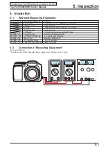
Страница 93: ...l use TV Monitor TV monitor minimum resolution 600 lines ZJ00580 100 Power Cable jig Common with adjustment JIG ZPU0512 100 SD CARD ULTRA2 1GB To check SD card recording ZJ00525 100 Macro Chart Resolution confirmation ZJ00885 100 LCD Inspection Data For LCD inspection ZJ01080 100 FxS5700 S700 Battery jig Battery low check 5 Inspection 5 1 Required Measuring Equipment 5 2 Connection of Measuring Equ...

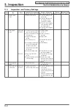
Страница 94: ...de dial setting 4 Turn the camera on 5 If messages prompting the user to set the language and date are appears press the button specified on the right 6 Check the display status 7 Press the EVF LCD button 8 Check for blemishes in the CCD live image 1 Applied voltage 5 0 0 1 V 2 Card for recording checking 3 Mode AUTO 4 Check that the camera beeps 5 DISP BACK 6 Check that the live image and text is ...

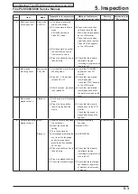
Страница 95: ...de 2 Press S1 S2 and then release S2 S1 3 After 5 seconds press and then release S1 1 Check that STANDBY appears on the LCD monitor 2 Check that movie audio recording begins Check that REC appears on the LCD monitor 3 Check that movie audio recording ends and that the data is recorded on the card 7 Movie audio playback check Playback 1 Set the camera to Playback mode 2 Press the 4 way button down ...

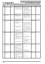
Страница 96: ...eable dust flecks or stains bright spots on the screen 3 Check that there are no noticeable dust flecks or stains smears flashing points etc on the screen 4 Play the above 2 frames and perform the same checks ZJ00885 100 12 Battery low check Movie 1 Connect the power supply jig to the Battery terminal 2 Set the power supply voltage 3 Set the Mode dial to Movie or Camera mode and turn the camera on 4 ...

Страница 97: ...pping inspection 1 Mode dial 2 SETUP frame no 3 Battery and cards not inserted 4 Internal memory 5 Battery cover 6 Power off 1 AUTO mode 2 New The default SETUP frame No setting is Continuous but to clear the number of frames in the frame number memory to zero you should always change the setting to New before turning the camera off 3 Normal 4 Check that the internal memory is formatted Excluding ...

Страница 98: ...FinePix S5800 S800 Service Manual 5 6 5 Inspection Confidential FUJIFILM Service Center Use Only MEMO ...

Страница 99: ... 2754 CD ROM A108 FZ06487 100 ALKALINE BATTERY A109 645 086 2106 USB CABLE A110 645 083 3823 AV CABLE A111 636 102 8455 STRAP A112 636 103 6870 LENS CAP A113 636 077 1093 STRAP CAP A114 636 105 3846 INSTRUCTION MANUAL ENGLISH A115 636 105 3853 INSTRUCTION MANUAL QUICK START ENGLISH Ref No Parts No Description Comment A116 636 105 3860 INSTRUCTION MANUAL QUICK START SPANISH A117 636 104 3243 WARRAN...

Страница 100: ... 5427 BAR CODE LABEL A105 636 101 4823 HDPE BAG A106 636 058 6888 BAG POLY INST A107 645 094 2754 CD ROM A108 FZ06487 100 ALKALINE BATTERY A109 645 086 2106 USB CABLE A110 645 083 3823 AV CABLE A111 636 102 8455 STRAP A112 636 103 6870 LENS CAP A113 636 077 1093 STRAP CAP A114 636 105 8506 CONFIRMATION LABEL A115 636 106 0219 COLOR LABEL L S5800B EU A113 A108 A112 A104 A102 A103 A101 A107 A109 A10...

Страница 101: ...NST A107 645 094 2754 CD ROM A108 FZ06487 100 ALKALINE BATTERY A109 645 086 2106 USB CABLE A110 645 083 3823 AV CABLE A111 636 102 8455 STRAP A112 636 103 6870 LENS CAP A113 636 077 1093 STRAP CAP A114 636 105 3846 INSTRUCTION MANUAL ENGLISH A115 636 105 3853 INSTRUCTION MANUAL QUICK START ENGLISH Ref No Parts No Description Comment A116 636 104 3205 WARRANTY CARD EG A117 636 105 8506 CONFIRMATION...

Страница 102: ... 058 6888 BAG POLY INST A107 645 094 2754 CD ROM A108 FZ06487 100 ALKALINE BATTERY A109 645 086 2106 USB CABLE A110 645 083 3823 AV CABLE A111 636 102 8455 STRAP A112 636 103 6870 LENS CAP A113 636 077 1093 STRAP CAP A114 636 105 3846 INSTRUCTION MANUAL ENGLISH A115 636 105 3853 INSTRUCTION MANUAL QUICK START ENGLISH Ref No Parts No Description Comment A116 636 105 8506 CONFIRMATION LABEL A117 636...

Страница 103: ...888 BAG POLY INST A107 645 094 2754 CD ROM A108 FZ06487 100 ALKALINE BATTERY A109 645 086 2106 USB CABLE A110 645 083 3823 AV CABLE A111 636 102 8455 STRAP A112 636 103 6870 LENS CAP A113 636 077 1093 STRAP CAP A114 636 092 2266 WARRANTY CARD CH A115 636 105 3891 INSTRUCTION MANUAL CHINESE CH Ref No Parts No Description Comment A116 BU03405 100 CERTIFICATE FC A117 BB19104 100 REGULATION SEAL A118 ...

Страница 104: ...FinePix S5800 S800 Service Manual 6 6 6 Parts List Confidential FUJIFILM Service Center Use Only MEMO ...

Страница 105: ...0 CABI BACK BLACK M225 636 102 7472 BUTTON BASE BLACK M226 636 102 7489 SELECT BUTTON M227 636 102 7816 MODE HOLDER PLATE M228 636 104 6008 SHEET MODE FPC M229 636 103 4357 MODE FPC M230 636 103 8874 SHEET MODE PLATE M231 636 102 7854 MODE DIAL SPRING M232 636 102 7847 MODE CLICK SPRING M233 636 102 7656 MODE DIAL HOLDER BLACK M234 636 102 7502 CARD COVER BLACK M235 636 090 7126 CARD LABEL M236 63...

Страница 106: ...SSY S800B US M333 636 103 8881 SHEET EVF A M334 645 092 2756 EVF UNIT M335 636 102 7588 LENS HOLDER TOP BLACK M336 636 103 5965 LENS SPACER M337 636 102 7601 AF LED HOLDER M338 636 105 1781 COMPL PWB TB 1 M339 636 102 7779 BATT TERMINAL A M340 636 102 7786 BATT TERMINAL B M341 636 100 1137 BATT COVER TERMINAL M342 636 105 1774 COMPL PWB PW 1 M343 636 104 5988 SHEET LEAD POWER M344 636 102 7793 STR...

Страница 107: ...B EE EU EG CH M333 636 103 8881 SHEET EVF A M334 645 092 2756 EVF UNIT M335 636 102 7588 LENS HOLDER TOP BLACK M336 636 103 5965 LENS SPACER M337 636 102 7601 AF LED HOLDER M338 636 105 1781 COMPL PWB TB 1 M339 636 102 7779 BATT TERMINAL A M340 636 102 7786 BATT TERMINAL B M341 636 100 1137 BATT COVER TERMINAL M342 636 105 1774 COMPL PWB PW 1 M343 636 104 5988 SHEET LEAD POWER M344 636 102 7793 ST...

Страница 108: ...EE EU EG CH M333 636 103 8881 SHEET EVF A M334 645 092 2756 EVF UNIT M335 636 102 7588 LENS HOLDER TOP BLACK M336 636 103 5965 LENS SPACER M337 636 102 7601 AF LED HOLDER M338 636 105 1781 COMPL PWB TB 1 M339 636 102 7779 BATT TERMINAL A M340 636 102 7786 BATT TERMINAL B M341 636 100 1137 BATT COVER TERMINAL M342 636 105 1774 COMPL PWB PW 1 M343 636 104 5988 SHEET LEAD POWER M344 636 102 7793 STRA...

Страница 109: ...7557 ST COVER BOTTOM BLACK M414 636 119 5379 ST COVER BOTTOM BLACK M415 636 104 6589 ST POP SPRING M415 636 119 5386 ST POP SPRING M416 636 103 2391 FLASH COVER M417 645 092 1384 LAMP ASSY M418 636 102 7618 FLASH HOLDER M419 645 069 2413 TRANS M420 636 102 4679 WIRE TRIG IN M421 636 102 4686 WIRE TRIG GND M422 613 212 7677 SI TUBE M423 636 103 8911 SHEET ST A M424 636 105 5864 ST COVER TOP S800B U...

Страница 110: ...57 ST COVER BOTTOM BLACK M414 636 119 5379 ST COVER BOTTOM BLACK M415 636 104 6589 ST POP SPRING M415 636 119 5386 ST POP SPRING M416 636 103 2391 FLASH COVER M417 645 092 1384 LAMP ASSY M418 636 102 7618 FLASH HOLDER M419 645 069 2413 TRANS M420 636 102 4679 WIRE TRIG IN M421 636 102 4686 WIRE TRIG GND M422 613 212 7677 SI TUBE M423 636 103 8911 SHEET ST A M424 636 105 5840 ST COVER TOP S5800B EU...

Страница 111: ...WITCH S3005 645 057 0773 PUSH SWITCH S3006 645 057 0773 PUSH SWITCH S3007 645 057 0773 PUSH SWITCH S3008 645 057 0773 PUSH SWITCH S3009 645 057 0773 PUSH SWITCH S3010 645 057 0773 PUSH SWITCH S3011 645 057 0773 PUSH SWITCH BATTERY Z3001 645 073 6544 RECHARGE BATTERY CONNECTOR CN101 645 088 7475 SOCKET FPC 51P CN110 645 075 9741 SOCKET 8P CN144 645 092 0233 SOCKET CARD XD CN171 645 069 5223 SOCKET ...

Страница 112: ...FinePix S5800 S800 Service Manual 6 14 6 Parts List Confidential FUJIFILM Service Center Use Only MEMO ...

Страница 113: ...t after sales srevice is performed accuratety keep a record here of the technical updates issued that cover this device Technical Update No Date Title Details Other 2007 151 21 Nov 2007 Service manual revisions Revised page P4 1 P4 6 and P4 22 2008 102 22 Sep 2008 Preventive measure for Flash pop up failure and Service Manual revisions Revised page P6 8 to P6 12 ...

Страница 114: ...Midtown West 7 3 Akasaka 9 chome Minato ku Tokyo 107 0052 Japan ...

Отзывы: