


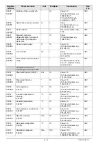

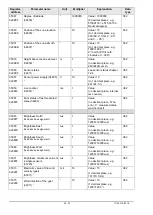


17 - 70
71130/11E/0318
5.3.2 Connection diagram for 16-core cable (function example)
Note:
- See the supplementary sheet "Werkseinstellung" with the factory settings for
precise function assignment.
- The pins A,B,C,H,I,K,L,M,N,O,P,R,S,T,U are electrically isolated from the
supply voltage.
Electrical connection
View of solder terminal
PIN Colour coding**
Assignment
Function
of socket outlet
T
PINK
Analogue 0..10V
Wind speed (m/s).
S
VIOLET
Analogue 0..10V
Wind direction (°).
O
RED-BLUE
Analogue 0..10V
Air temperature (°C).
N
GREY-PINK
Analogue 0..10V
Relative humidity (%).
C
BROWN-GREEN
Analogue 0..10V
Air pressure (hPA).
B
WHITE-YELLOW
Analogue 0..10V
Brightness (lux).
A
WHITE-GREEN
Analogue 0..10V
Brightness direction (°).
P
YELLOW-BROWN Analogue 0..10V
Precipitation intensity.
H
BLUE
GND isolated
Analogue earth.
I
GREY
GND isolated
Analogue earth.
L
YELLOW
TXD+, RXD+ (HD) Serial interface (RS485).
K
GREEN
TXD-, RXD- (HD) Serial interface (RS485).
U
BROWN
RXD+ (full duplex)
Serial interface (RS485).
M
WHITE
RXD- (full duplex)
Serial interface (RS485).
R
not assigned
(-)24V feedback
(-) Power supply*.
E
RED
(+)24V AC/DC
nom.
(+) Power supply*.
F
not assigned
(+)24V AC/DC
nom.
(+) Power supply*.
D
BLACK
(-)24V AC/DC nom. (-) Power supply*.
G
not assigned
(-)24V AC/DC nom. (-) Power supply*.
SH
GREEN/YELLOW
CABLE SHIELD
Shielding from electric fields.
* Reverse voltage protection.
** The above colour coding scheme only applies to cables of the type SABIX D315 FRNC
16 x 0.25.
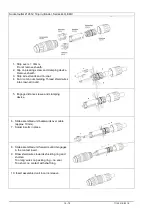
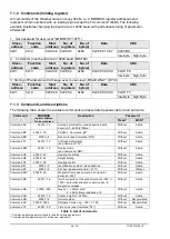
5.3.3 Connection with optional 16-core cable 509311
The optional 509311 cable is a ready prepared 16-core cable, which has a plug connector on the
transmitter side, and open, colour-coded wire ends on the user side.
See section 5.3.2 for cable assignment.