background image

M6500 Series NE Configuration Manual

32

3. DCN Configuration

3.1. DCN Introduction

DCN (Data Communication Network) controls remote NE through optical fiber and forms the in-band
management channel of NE through GCC.

OTN provides a dedicated communication channel (GCC0/1/2/1+2) which can realize in-band management.

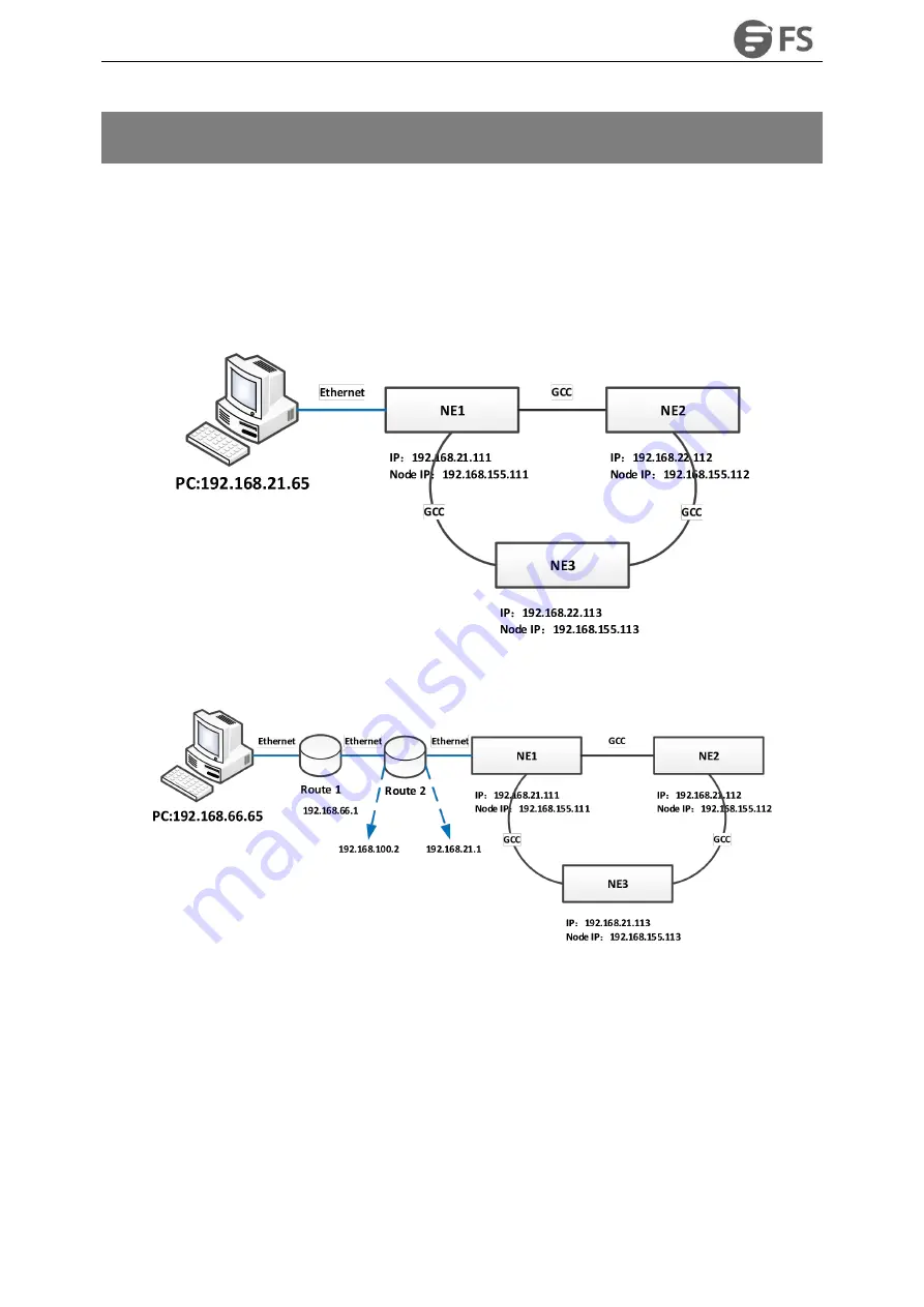
The basic environment of DCN is as shown in the figure below:

Figure3-1 Basic Environment Map of PC Direct Connection

Figure3-2 Basic Environment Map of Connection between PC and Router

3.2. Configuration Steps

3.2.1. Direct Connection between PC and Device

Open the GCC channel of the occupied port

Configure the node IP of the gateway NE and enable OSPF function

Configure the node IP of the remote NE

Содержание M6500 Series

Страница 1: ...M6500 Series NE Configuration Manual M6500 Series 100G 200G Muxponder Transponder NE Configuration Manual Copyright 2009 2020 FS COM All Rights Reserved...

Страница 2: ...6 2 4 4 Add a Line card 17 2 4 5 Delete a Line card 18 2 5 NE IP Address Management 19 2 5 1 Node IP Configuration 19 2 5 2 NMS IP1 Configuration 20 2 5 3 NMS IP2 Configuration 20 2 5 4 Local NMS IP L...

Страница 3: ...Indicator Information 42 4 2 1 NMU Board 43 4 2 2 System Interface LED Indicator 44 4 2 3 Service Board LED Indicator 44 4 2 4 Fan Tray LED Indicator 45 4 2 5 Port LED Indicator of Service Board 45 4...

Страница 4: ...nal Cross Connection with Protection 68 5 2 Service Type 69 5 2 1 Service Type 69 5 2 2 Service Mapping 70 5 2 2 1 AMP 70 5 2 2 2 BMP 71 5 2 2 3 GMP 71 5 2 2 4 GFP F 72 5 2 2 5 GFP Fextp 72 5 3 Servic...

Страница 5: ...ion Example 122 8 Alarm Management 132 8 1 Alarm Management Introduction 132 8 2 Main Interface of Alarm Management 132 8 2 1 Current Alarm 132 8 2 2 History Alarm 138 8 3 Alarm Configuration 140 8 3...

Страница 6: ...58 9 2 4 3 Error Generation Conditions for Monitoring Parameters 159 9 2 4 4 OTUk ODUk Monitoring Data Reset 159 9 2 4 5 OTUk ODUk Monitoring Data Shown As 160 9 2 5 Current Performance Statistics of...

Страница 7: ...ODUk History Monitoring Parameters Introduction 174 9 3 4 2 View OTUk ODUk History Monitoring Information 175 9 3 4 3 Export OTUk ODUk History Monitoring Information 176 9 3 5 History Performance Stat...

Страница 8: ...nts Chapter 6 Overhead Configuration This chapter introduces the traditional overhead configuration scheme of OTN Chapter 7 SNC Protection Configuration This chapter introduces the SNC protection conf...

Страница 9: ...requires special attention to ensure the success of the operation or the normal work of the device A skill or a knack which helps to solve a problem and save time The necessary supplement and explana...

Страница 10: ...1 Figure 1 1 M6500 Service Configuration Process M Series NMS system mainly contains operations such as parameter configuration of single card service protection in band management as well as alarm q...

Страница 11: ...ect one end to the network card interface of the host computer and connect the other end to the Ethernet port of HUB Take another network cable and connect one end to the Ethernet port of HUB and conn...

Страница 12: ...M6500 Series NE Configuration Manual 11 Figure 1 3 Start NMS Server...

Страница 13: ...ss in the following passage Moreover it will focus on the parameter configuration related to M6500in each step and only the sections of the reference book will be provided for the common configuration...

Страница 14: ...gure2 1 Flow Chart of Create Network Topology 2 2 Login NMS Interface Prerequisite The installation of NMS system is completed and NMS server has been started Steps Open Google Chrome and type in the...

Страница 15: ...login Default user name root Default password public Figure2 2 Login NMS System 2 3 Create Groups Steps to add a group 1 Click on Global View and select Group Configuration on the right 2 Enter the no...

Страница 16: ...Add Group module 4 Click on Apply to add a child group Figure2 4 Add a Child Group 2 4 Add NE 2 4 1 Add NE Steps 1 Click on the group which has been added and select Group Configuration on the right...

Страница 17: ...ed and select Group Configuration on the right 2 Modify the Modify Group module Only the display name of the network element can be modified here Figure2 6 Modify NE 2 4 3 Delete NE Steps 1 Click on t...

Страница 18: ...Delete NE 2 4 4 Add a Line card Steps 1 Select an empty slot on the added network element 2 Click on the empty slot and select Card Mode Configuration module Figure2 8 Add a line card 3 Select the ca...

Страница 19: ...4 5 Delete a Line card Prerequisite The line card to be deleted has no single board crossover or cross board crossover services otherwise it cannot be deleted Steps 1 Click on the line card and selec...

Страница 20: ...agement IP address Can be modified by the client Local NMS IP address default IP address 192 168 126 2 Use of DCN The NMS system of the transmission products will manage thousands of network elements...

Страница 21: ...guration on the right 3 Input NMS IP1 address in the NMS IP1 MGMT_Port1 3 4 box 4 Click on Apply to save the configuration Figure2 14 NMS IP1 Configuration 2 5 3 NMS IP2 Configuration Steps 1 Click on...

Страница 22: ...ocal NMS IP address is 192 168 126 1 The default Subnet Mask is 255 255 255 252 Figure2 16 Local NMS IP Configuration 2 5 5 Gateway Configuration Steps 1 Click on the NE which has been added 2 Click o...

Страница 23: ...og Upload NMU LC Card BSP Upgrade Performance Management During the use of the FTP server one and only one server address can be configured For different FTP servers different FTP server addresses can...

Страница 24: ...k on the NE which has been added 2 Click on Server Configuration on the menu bar 3 Select SNMP Trap Configuration module Figure2 19 SNMP Trap Configuration 4 Click on Add button to add SNMP Trap infor...

Страница 25: ...8 1 Configure NTP Server Click on the NE which has been added Click on Server Configuration on the right Select NTP Configuration module to make relevant configuration Steps 1 Click on the NE which h...

Страница 26: ...e configuration Figure2 22 NTP Server Configuration 2 8 2 Configure NE Time Steps 1 Click on the NE which has been added 2 Click on NE Configuration on the right to enter the configuration interface F...

Страница 27: ...modification of the original configuration caused by the abnormal operation of the network element by the engineer the previous configuration is downloaded from the local NMS server to the network el...

Страница 28: ...Save 2 9 2 Upload NE Configuration Click on the NE which has been added Click on NE Configuration on the right Click on Configuration Data Upload Figure2 26 Configuration Data Upload Input the name of...

Страница 29: ...hich has been added Click on NE Configuration on the right Select Configuration Data Download module Figure2 28 Configuration Data Download Select the configuration file which needs to be downloaded a...

Страница 30: ...onfiguration Manual 29 Figure2 30 Default Configuration Data Restore 2 10 Create Fiber Optic 2 10 1 Adjust NE Layout Click on Global View and click on NE or node in the global view and then drag it to...

Страница 31: ...Figure2 31 Adjust NE Layout 2 10 2 Create Link between NEs Click on Connect button in the global view Figure2 32 Click Connect Button Input name NE IP address shelf number slot number and port number...

Страница 32: ...M6500 Series NE Configuration Manual 31 Figure2 33 Create Link between NEs 2 10 3 Save Layout Click on Save button in the global view Figure2 35 Save Layout...

Страница 33: ...nel GCC0 1 2 1 2 which can realize in band management The basic environment of DCN is as shown in the figure below Figure3 1 Basic Environment Map of PC Direct Connection Figure3 2 Basic Environment M...

Страница 34: ...NE Configure routing on the NMS server Connect the occupied port through optical fiber Manage the device through the node IP 3 3 Configuration Example Here we take M6500 MXP10 as an example 3 3 1 Dir...

Страница 35: ...guration Manual 34 Figure3 4 Enable OTU4 OCh OTU4 Port Click on OTU2 OTU2e OTU4 OCh OTU4 or ODU2 ODU2e ODU4 which is on the left of Port Configuration interface Figure3 5 Preparation before Enable GCC...

Страница 36: ...hen click on DCN in the lower to enter DCN configuration interface Select GCC type The GCC type of OTU layer is GCC0 and the GCC type of ODU layer is GCC1 GCC2 and GCC1 2 as shown in the figure below...

Страница 37: ...the gateway NE and enable OSPF function Select a NE as the gateway NE After selecting the NE click on MGMT IP Configuration and select MGMT IP Configuration module Figure3 10 Select NE and Manage IP...

Страница 38: ...that to configure the node IP of gateway NE However the node IP should be different from that of the gateway NE and the IP of NMS IP1 cannot be in the same network segment with the gateway NE IP Figur...

Страница 39: ...ode IP unplug the network cable of the remote NE and add the two IP addresses of 192 168 155 111 and 192 168 155 112 to the NMS system After the IP addresses are successfully added normal management o...

Страница 40: ...500 Series NE Configuration Manual 39 Figure3 16 Enable Default Route Redistribution Function of the Gateway NE Add Configuration 2 Set the gateway of the remote NE as 0 0 0 0 Figure3 17 Modify Gatewa...

Страница 41: ...omputer route add 192 168 155 0 mask 255 255 0 192 168 155 1 Here the network segment of 192 168 155 0 is the actually configured node IP segment 192 168 66 1 is the network segment of NMS server loca...

Страница 42: ...on Google Browser localhost 9090 log in to the NMS root account 5 The M Series NMS interface is displayed after successful login 4 1 Shelf Information Select NE and click on Shelf01 then click on Shel...

Страница 43: ...rface of 5U device is as shown in the figure below Figure 4 4 M6500 CH5U Shelf Information 4 2 LED Indicator Information The LED indicators on different series of network elements ports boards systems...

Страница 44: ...e software is not started NA ACTIVE Green Light On NMU is Active Green Light Off NMU is Standby NA FAULT ALM Red Light Slow Flash There is latch open alarm Red Light On Alarm exists in NE Red Light Of...

Страница 45: ...an Tray CR Red Light On There is Critical alarm MJ Orange Light On There is Major alarm MN Yellow Light On There is Minor alarm On NMU Board CR Red Light On There is Critical alarm MJ Orange Light On...

Страница 46: ...r Off The port is disabled Red Light Quick Blink There is mismatch alarm of the port Red Light On There is los alarm of the port Green Light On There is no los or mismatch alarm of the port Off The po...

Страница 47: ...e is power failure PWR1 Monochrome Off The power tray is not powered Green Light On Normal power supply NA PWR2 Monochrome Off The power tray is not powered Green Light On Normal power supply NA 4 3 V...

Страница 48: ...pes client side port and line side system side port Client side port type supports FE GE 10GE 40GE and 100GE STM 1 4 16 OC 3 12 48 STM 64 OC 192 and OTU2 2e OTU3 OTU4 For line side system side port ty...

Страница 49: ...that of other boards When the port 2 is disabled it is in unused status as shown in the figure below Figure4 9 M6500 TMXP2 Board Client Side Port Disabled Interface While enabling the port firstly sel...

Страница 50: ...ent Side Port 4 4 1 1 Interface Configuration Select NE Slot 1 click on Port1 and select Port Management on the right the port management interface shows up Select the interface options of the Port Co...

Страница 51: ...interface shows up here we take ODU2 corresponding to XGE_GFPF port mode as an example Click on ODU2 option from Port Configuration in this interface as shown in the figure below It shows ODU2 toolba...

Страница 52: ...p here we take ODU2e corresponding to XGE_BMP port mode as an example Click on ODU2e option from Port Configuration in this interface as shown in the figure below It shows ODU2e toolbar interface Figu...

Страница 53: ...terface pops up Click on OTU2 option from Port Configuration in this interface as shown in the figure below It shows OTU2 toolbar interface Figure4 17 OTU2 Toolbar Interface OTU2e Configuration Select...

Страница 54: ...k on ODU4 option from Port Configuration in this interface as shown in the figure below It shows ODU4 toolbar interface Figure4 19 ODU4 Toolbar Interface 4 4 1 5 OTU4 Configuration Select NE Slot 2 cl...

Страница 55: ...erface shows up here we take OTUC2 corresponding to OCh OTUC2 port mode as an example Click on OTUC2 option from Port Configuration in this interface as shown in the figure below It shows OTUC2 toolba...

Страница 56: ...Series NE Configuration Manual 55 Figure4 22 M6500 MXP10 Port Mode Figure4 23 M6500 TMXP2 Port Mode Figure4 24 M6500 TMXP5 Port Mode Table4 10 Parameter Description of OTN Board Board Interface Descri...

Страница 57: ...agement Support SNC I and SNC N transmission protection M6500 TMXP5 1 100G 200G line side interface CFP2 2 100G QSFP28 or 4 40G client side interface QSFP or 20 4x5 10G client side interface The clien...

Страница 58: ...face is under the port configuration interface menu 4 5 1 SFP SFP Optical Transceiver Information The SFP and SFP optical module information of M Series NMS system is not separately distinguished Open...

Страница 59: ...Figure4 27 Parameter Information of SFP SFP Optical Transceiver 4 5 2 WDM CFP Optical Transceiver Information Figure4 28 Parameter Information of WDM CFP Optical Transceiver Figure4 29 Parameter Info...

Страница 60: ...de as OCh OTU4 insert a WDM CFP optical module and select the interface you can configure the working wavelength and transmitting optical power of the optical module as shown in the figure below Figur...

Страница 61: ...l Transceiver Figure 4 33 Parameter of WDM CFP2 Optical Transceiver 4 5 5 WDM CFP2 Optical Transceiver Configuration Configure the port mode as OCh OTUC2 insert a WDM CFP2 optical module and select th...

Страница 62: ...M6500 Series NE Configuration Manual 61 Figure 4 34 Configure Operating Wavelength of WDM CFP2 Figure 4 35 Configure WDM CFP2 Transmit Optical Power...

Страница 63: ...M6500 Series NE Configuration Manual 62 Figure 4 34 Parameter Reading of WDM CFP2 Optical Transceiver...

Страница 64: ...he service is transmitted from site A site Z You can choose site A or site Z as the protection site either of them If site A is selected as the protection site the service will be received only When t...

Страница 65: ...n the figure below Figure5 3 Protection Schematic Diagram 5 1 1 Unidirectional Cross Connection without Protection Select NE click on Shelf01 and select Add button in SNC Configuration of Business Con...

Страница 66: ...t Protection 5 1 2 Bidirectional Cross Connection without Protection Select NE click on Shelf01 and select Add button in SNC Configuration of Business Configuration interface you can create bidirectio...

Страница 67: ...lick on Shelf click on Business Configuration and select Add button in SNC Configuration of Business Configuration interface you can create unidirectional cross connection with protection here we take...

Страница 68: ...M6500 Series NE Configuration Manual 67 Figure5 8 Configuration of Unidirectional Cross Connection with Protection...

Страница 69: ...t Add button in SNC Configuration of Business Configuration interface you can create bidirectional cross connection with protection here we take M6500 MXP10 as an example the 11 ports from Port 1 Port...

Страница 70: ...Bidirectional Cross Connection with Protection Figure5 11 Configuration Result of Bidirectional Cross Connection with Protection 5 2 Service Type 5 2 1 Service Type Select NE Slot 1 click on Port1 an...

Страница 71: ...line is port mode and the right is the mapping mode OTU signal is not included Figure5 14 Mapping Mode Interface 5 2 2 1 AMP AMP Asynchronous Mapping Procedure has no restrictions on the structure of...

Страница 72: ...5 2 2 3 GMP For GMP Generic Mapping Procedure in all cases such as the maximum ppm frequency offset of the client signal and the minimum ppm frequency offset of the server signal the rate of the serv...

Страница 73: ...is method data processing is performed after receiving a complete data frame which is most suitable for packet data with variable length such as Ethernet services Here we take M6500 MXP10 board as an...

Страница 74: ...M6500 Series NE Configuration Manual 73 Figure5 19 XGE_GFPFextp Mapping Mode 5 3 Service Configuration Process Figure5 20 Service Configuration Process...

Страница 75: ...s SFP 5 4 1 1 Service Type Line Side Port Select NE Slot 1 click on Port11 and select Port Management on the right the operation interface is as shown in the figure below Figure5 21 M6500 MXP10 Line S...

Страница 76: ...e5 23 M6500 MXP10 Client Side Port Information The client side port management interface is as shown in the figure below and the service type can be selected in port mode Figure5 24 M6500 MXP10 Client...

Страница 77: ...ion Click on ODU4 button and the interface is as shown in the figure below Select ODU4 to demultiplex to ODU2 ODU2e Figure5 26 M6500 MXP10 Demultiplexing Configuration Interface ODU4 can be demultiple...

Страница 78: ...M6500 Series NE Configuration Manual 77 Figure5 27 M6500 MXP10 Demultiplexing ODU2e Configuration The result when it is with full configuration of 10 ODU2e is as shown in the figure below...

Страница 79: ...Cross Connection Configuration For example if we need to create bidirectional cross connection with protection of port 1 to port 11 the operation is as follows Select XGE_BMP at the client side and se...

Страница 80: ...M6500 Series NE Configuration Manual 79 Figure5 29 M6500 MXP10 Bidirectional Cross Connection with Protection The following figure shows that the cross connection is successfully established...

Страница 81: ...M6500 MXP10 line side which are respectively G709FEC SDFEC1 SDFEC2 SDFEC3 SDFEC1_Non diff SDFEC2_Non diff SDFEC3_Non diff SDFEC2 is the default mode as shown in the figure below Figure5 31 FEC Configu...

Страница 82: ...OTU2e Port 5 4 2 M6500 TMXP2 The port type of M6500 TMXP2 includes 1 port 3 100G line side interface CFP 1 port 1 100G rate client side interface QSFP28 or 2 port 1 2 40G client side interfaces QSFP...

Страница 83: ...as shown in the figure below and the service type can be selected in port mode Figure5 35 M6500 TMXP2 Line Side Port Interface Client Side 100G Port Select NE Slot 2 click on Port1 and select Port Ma...

Страница 84: ...t Side 40G Port The current board mode is 100G you need to change the board mode to 40G mode Select NE 10 32 130 220 Slot2 click on Slot2 and select Card Mode Configuration module on the right as show...

Страница 85: ...s performed The latest mode of M6500 TMXP2 board is synchronized The operation steps are as follows select NE and click and select NE Management on the right then click synchronization button on the r...

Страница 86: ...ment on the right the interface is as shown in the figure below Figure5 44 M6500 TMXP2 Client Side 40G Port Interface 5 4 2 2 Time Slot Configuration When the board is in 100G mode there is no need to...

Страница 87: ...TMXP2 TP Multiplexing The interface is as shown in the figure below Select ODU4 to demultiplex to ODU3 ODU2 ODU2e are unavailable Figure5 46 M6500 TMXP2 Demultiplexing Configuration Interface ODU4 ca...

Страница 88: ...igure5 48 Configuration Result of M6500 TMXP2 Demultiplexing 2 ODU3 5 4 2 3 Cross Connection Configuration For example if we need to create bidirectional cross connection without protection of port 1...

Страница 89: ...ection without Protection The following figure shows that the cross connection is successfully established Figure5 50 Successful Establishment of M6500 TMXP2 Bidirectional Cross Connection without Pro...

Страница 90: ...ick on Port1 and select Port Management on the right and then select OTU4 as the port mode In OTU4 interface under Port Configuration select FEC type to view the configuration There is only one defaul...

Страница 91: ...ort 3 100G client side interfaces QSFP28 and 3 ports 4 6 10G client side interfaces QSFP 4 Ports 2 5 40G client side ports QSFP and 1 port 6 10G client side ports QSFP 5 ports 2 6 10G client side port...

Страница 92: ...Slot 1 and select Card Mode Configuration module on the right the steps are shown in the figure below Figure5 56 M6500 TMXP5 Board configuration operation steps After selection the card mode selection...

Страница 93: ...itialization mode as shown below Figure5 59 M6500 TMXP5 Board initialization After a while perform NE synchronization and synchronize the latest mode of the M6500 TMXP5 board The operation steps are a...

Страница 94: ...ard card mode is successfully switched as shown in the figure below Figure5 61 The board mode switch successfully Client Side 100G Select the NE Slot 1 click on Port 3 and select Port Configuration on...

Страница 95: ...nt side 100G port interface Client side 40G port First switch the card mode to the corresponding mode Choose NE Slot 1 click on Port 5 and choose Port management on the right as shown in below Image5...

Страница 96: ...he time slot and the other board modes all need to configure the time slot Take TMXP5 4X40G 4X10G as an example Select the NE Slot1 and on the right side there is TP Multiplexing Structure module the...

Страница 97: ...5 Demultiplexing configuration interface Each ODU4 can be demultiplexed into 2 ODU3 in total each ODU3 is configured with 31 time slots and 2 ODU2 2e each ODU2 2e is configured with 8 time slots Figur...

Страница 98: ...tion Manual 97 Figure5 69 M6500 TMXP5 Demultiplexing ODU2 2e time slot configuration Fully configure 2 ODU3 and 2 ODU2 2e is shown as below figure Figure5 70 M6500 TMXP5 demultiplexing 2 ODU3 and ODU2...

Страница 99: ...side and OCh OTUC2 on the line side corresponding to the establishment of ODU3 crossover as shown in the following figure Figure5 71 M6500 TMXP5Two way cross without protection The cross establishment...

Страница 100: ..._8QAM SDFEC2_8QAM SDFEC3_8QAM SDFEC1_16QAM SDFEC2_16QAM SDFEC3_16QAM and when the line side is 7 in the default mode SDFEC3_16QAM is the default mode The FEC modes are G709FEC SDFEC1 SDFEC2 SDFEC3 SDF...

Страница 101: ...ort mode select the FEC Type option on the OTU3 interface under Port Configuration on the client side there are 4 FEC modes for 40G namely no FEC G709FEC I 4EFEC I 7EFEC among which G709FEC is the def...

Страница 102: ...nt side 40G Port FEC configuration 5 5 Configuration Example 5 5 1 Configuration Example of Ring Network Service Here we take the ring network of Site A Site B and Site C in M6500 TMXP2 board access 1...

Страница 103: ...M6500 Series NE Configuration Manual 102 Figure5 78 Configure Line Side Signal Mode Create cross board two way SNC cross connection for ODU4 of the client side port1 to port3...

Страница 104: ...Respectively create the two way SNC cross connection with protection of port1 to port3 primary port3 standby at Site A and Site C Ensure that the client side service types including mapping methods of...

Страница 105: ...M6500 Series NE Configuration Manual 104 Figure5 80 Site to Site Primary and Standby Protection Environment...

Страница 106: ...ng cards The general principles are as follows priority is determined in sequence 1 SM must be terminated between the network elements at both ends of the power layer service and the intermediate netw...

Страница 107: ...cal end and opposite end of M6500 MXP10 board Specific service is configured according to actual demand OTU4 service is configured for port 11 of the local end and opposite end board Specific service...

Страница 108: ...M6500 Series NE Configuration Manual 107 Figure6 2 Select Port Service Figure6 3 Enter TP Multiplexing Interface Figure6 4 TP Multiplexing Configuration Step 1...

Страница 109: ...M6500 Series NE Configuration Manual 108 Figure6 5 TP Multiplexing Configuration Step 2...

Страница 110: ...pposite ends to configure Send TTI and Expect to Receive TTI of SM overhead for the corresponding port The configuration rules are as shown in the table above Configure the expected and sent source ac...

Страница 111: ...r arbitrary strings 6 2 2 PM Configuration Steps Activate the connection and monitoring enablement of PM overhead In M Series NMS the service XGE_BMP is configured for port 1 of the local end and oppo...

Страница 112: ...the signal received on the line side is correct For client side Port 1 If the status of ODU layer is client side signal terminated then both expected TTI and sent TTI can be set They are used to test...

Страница 113: ...M6500 Series NE Configuration Manual 112 Figure6 12 Set Line Side PM Overhead...

Страница 114: ...M6500 Series NE Configuration Manual 113 Figure6 13 Enter Client Side Port Management Interface Figure6 14 Enter Client Side ODU2 Management Interface...

Страница 115: ...ion access point identifier DAPI Here ODU2 ODU2e is prohibited to set sent SAPI and DAPI Enter ODU2 ODU2e interface of the client side local and opposite ends to configure expected receiving TTI and s...

Страница 116: ...M6500 Series NE Configuration Manual 115 Figure6 16 Configure Line Side Port TTI...

Страница 117: ...M6500 Series NE Configuration Manual 116 Figure6 17 Configure Client Side Local End Port TTI...

Страница 118: ...M6500 Series NE Configuration Manual 117 Figure6 18 Configure Client Side Opposite End Port TTI...

Страница 119: ...nts of the local end and opposite end client side signals should be configured with the same service such as XGE_GFPF service Specific configuration needs to be made according to actual needs The capa...

Страница 120: ...at both ends and then set the values of sending TTI and expected TTI For detailed configuration please see the detailed steps described in 6 2 1 If the values of sending TTI and receiving TTI at both...

Страница 121: ...ic service needs to be configured according to actual demand Enable the monitoring function of PM overhead of client side port at both ends on ODU2 layer Here the status of ODU2 layer is client end si...

Страница 122: ...to the protection channel The switch time is less than 50ms so the service interruption can not be perceived and the service can run normally Figure7 1 Schematic Diagram of SNC Protection Service Env...

Страница 123: ...stent Protection Switching Command Settings Manually select the issuing external command Delete Protection Settings Manually delete the protection channel working channel 7 3 Configuration Example The...

Страница 124: ...Here we take the 10G service cross board protection of M6500 MXP10 board as an example to introduce the configuration process of SNC services 1 Insert a M6500 MXP10 board in M6500 and open the NMS in...

Страница 125: ...then click on Apply Figure7 4 Configure Client Side Service 2 Here we take Port 11 of Slot 1 and Port 11 of pair Slot 17 as the line side port Click on the port and select Port Management on the righ...

Страница 126: ...Line Side Service 3 Click on the service board and select TP Multiplexing Structure Figure7 6 TP Multiplexing Structure Select the appropriate time slot to demultiplex to the low order ODU layer so a...

Страница 127: ...M6500 Series NE Configuration Manual 126 Figure7 7 Select Time Slot Demultiplexing 4 Select SNC cross connection type bidirectional with protection or unidirectional with protection...

Страница 128: ...ion Manual 127 Figure7 8 Select Cross Connection Type 5 Select the service capacity that is the corresponding ODU time slot Figure7 9 Select Service Capacity 6 Select SNC protection mode Site A protec...

Страница 129: ...M6500 Series NE Configuration Manual 128 Figure7 10 Select Protection Mode...

Страница 130: ...ction of SNC protection service then click on PPG option of the created SNC cross connection with protection Figure7 11 Click Protection Group Select the protection type SNC I or SNC N Figure7 12 Sele...

Страница 131: ...tion cross connection Figure7 14 Protection Switching Settings Manually select to issue protection switching command The command priority is clear lock protection switching force switch to working cha...

Страница 132: ...ction Switching Command 10 Click on Unprotect option of the created SNC protection cross connection Figure8 16 Delete Protection You can manually select to delete the working channel or the protection...

Страница 133: ...imary secondary and warning 8 2 Main Interface of Alarm Management After logging in the NMS system click on Maintain on the navigation bar left click on the Alarm Management menu the alarm management...

Страница 134: ...tions of these buttons are The function of Ack button is to confirm the selected alarm By ticking the check box on the left of the alarm to be confirmed and clicking the Ack button the selected alarms...

Страница 135: ...cel confirmed alarms and return them to unconfirmed state The operation method is similar like that to confirm alarm select the alarm to be canceled confirmation click the Unack button click on Apply...

Страница 136: ...ude NE IP specified slot of specified IP specified port of specified slot alarm creation and termination time i e alarm generation period the beginning and ending time of alarm clearance alarm level a...

Страница 137: ...Refresh button is a button which can move right and left It can switch from refresh to close or from close to refresh by clicking the button The current page is refreshed every 10 seconds when it is...

Страница 138: ...M6500 Series NE Configuration Manual 137 Figure8 14 Alarm Details Figure8 15 Alarm Document Link...

Страница 139: ...hat generates alarm The alarm source is the specific slot or port information of NE which generates alarm Alarm name alarm type status generation time clearance time confirmation status confirmer and...

Страница 140: ...le you want to save in the dialog box After saving it will prompt to save the path The exported data is saved in Excel format Figure8 18 Export History Alarm The path to save the data is NMS Installat...

Страница 141: ...only be confirmation state There are two types of confirmer which are automatic confirmation and current login user confirmation such as root 8 3 Alarm Configuration 8 3 1 Alarm Configuration Click on...

Страница 142: ...n Alarm Name All the alarms on NE are contained in alarm name Alarm Level Configuration The specified alarm level can be set for the specified alarm There are four optional levels emergency primary se...

Страница 143: ...he Emergency Level Alarm Tree you can find that by default all the Emergency Level Alarms are selected The designated alarms or all the alarms can be checked or the check can be canceled In applicatio...

Страница 144: ...when there is an alarm on the NMS system the NMS server will continue to issue an alarm sound after enabling this function so as to indicate that there is an alarm on the NMS system Currently the NMS...

Страница 145: ...ons include network element slot port PM monitoring cycle performance monitoring status There are three kinds of monitoring status enable disable and all The three kinds of monitoring status can be vi...

Страница 146: ...mance statistics can be viewed The 24 hour performance monitoring operation is the same as the 15 minute operation as shown in the figure below Figure9 1 Enable Monitoring Points Since the enablement...

Страница 147: ...select the previous multiple checkboxes then click the button on the table Enable PMP to enable the monitoring of selected performance as shown in the figure below Figure9 4 Batch Enabling Monitoring...

Страница 148: ...ormance monitoring point is disabled the relevant data of the current performance statistics can not be viewed as shown in the figure below Figure9 6 Disable Monitoring Point Each monitoring point can...

Страница 149: ...able the performance monitoring point 1 The current performance data cannot be acquired 2 The history performance data which has been saved can be viewed by the NMS system and the user 3 When the user...

Страница 150: ...itoring Information Select the appropriate network elements slots ports and monitoring cycle through the selection box above the menu the optical power value of a certain network element slot port wil...

Страница 151: ...e Taking 15 minute operation as an example you can click on Reset behind each piece of monitoring record to perform resetting of a single piece of monitoring record or you can select the first box to...

Страница 152: ...ptical Module of Optical Power Not in Position Here are the situations when the monitoring data of optical power for the board is shown as 1 When the board is not in position or is pre configured with...

Страница 153: ...average optical signal to noise ratio OSNR suspicious interval marker running time and reset operation The performance parameters of OCh will be enabled or disabled at the same time Figure9 21 OCh Mo...

Страница 154: ...Data When the current OCh monitoring data needs to be reset and to restart the monitoring the 15 minute and 24 hour operation steps are the same Taking 15 minute operation as an example you can click...

Страница 155: ...time is normal and counts from 0 as shown in the figure below Figure9 26 Optical Module of OCh Not In Position Here are the situations when the monitoring data for the board is shown as NA 1 When the...

Страница 156: ...ce near end monitoring point for FEC Optical module is inserted into the monitoring port FEC data and corresponding generation time stamp which are currently read will be displayed After the port is e...

Страница 157: ...e first box to reset as shown in the figure below Figure9 32 FEC Reset Then click on Apply button as shown in the figure it will show that the operation is successful After that click on Refresh butto...

Страница 158: ...ard is enabled all the non time stamp data will be shown as and all the time stamps will be shown as The suspicious interval is marked as untrustworthy and the running time is always 0 without any cha...

Страница 159: ...es of the port are not OTU2 OTU2e Optical module is inserted into the monitoring port OTUk ODUk monitoring data which is currently read will be displayed After the port is enabled the suspicious inter...

Страница 160: ...SES are generated when high rate bit error is inserted by the meter The continuous 10S of SES will become a UAS If the high rate bit error of the meter keeps then ES and SES stops counting but UAS wi...

Страница 161: ...as The suspicious interval marker is trustworthy or untrustworthy after 900 86400 seconds The running time is normal and counts from 0 as shown in the figure below Figure9 43 Optical Module of OTUk O...

Страница 162: ...ement slot port will be displayed The monitoring point of SDH only includes the near end and the monitoring direction only includes entrance Generally the client port which is not OTU is corresponding...

Страница 163: ...he same Taking 15 minute operation as an example you can click on Reset behind each piece of monitoring record to perform resetting of a single piece of monitoring record or you can select the first b...

Страница 164: ...untrustworthy The running time is normal and counts from 0 as shown in the figure below Figure9 51 Optical Module of SDH Regeneration Segment Not In Position Here are the situations when the monitori...

Страница 165: ...n the figure select the appropriate network elements slots ports and monitoring cycle through the selection box above the menu the Ethernet value of a certain network element slot port will be display...

Страница 166: ...e figure it will show that the operation is successful After that click on Refresh button to refresh the whole page At this time the suspicious interval marker will become from untrustworthy to trustw...

Страница 167: ...uspicious interval is marked as untrustworthy and the running time counts from 0 without any change as shown in the figure below Figure9 61 Ethernet Monitoring Data When Mismatched 9 3 History Perform...

Страница 168: ...in the right menu The maximum optical power minimum optical power and average optical power can be all selected or only select one or two of them to check After that click Apply button on the lower r...

Страница 169: ...click on Apply button in the lower right corner the history data of all the optical power records on this port will be displayed as shown in the figure below Figure9 65 15 Minute Tabular History Data...

Страница 170: ...3 2 1 OCh History Monitoring Parameters Introduction The monitoring parameter of the history monitoring point for OCh includes time interval which is a shortcut to choose the time There are three opt...

Страница 171: ...nu and then select the time interval performance monitoring point and parameters which need to be monitored in the right menu Parameters to be monitored can be all selected or only select one or two o...

Страница 172: ...l be displayed as shown in the figure below Figure9 71 15 Minute Tabular History Data of OCh 9 3 2 3 Export OCh History Monitoring Information To save the history data you can click on the upp er Expo...

Страница 173: ...tory Monitoring Information 15minutes and 24hours of FEC history data operation and display are the same form Here we take 15 minute FEC history monitoring point as an example Choose the appropriate n...

Страница 174: ...e table the interface as shown in the figure below appears Figure9 76 15 Minute Tabular Interface of FEC Click the time interval shortcut in the right menu or select the required time interval in Dura...

Страница 175: ...ntered as the file name and then click on Apply button it will prompt that the export is successful as shown in the figure below Figure9 79 Successfully Export Data of FEC 9 3 4 OTUk ODUk History Perf...

Страница 176: ...ing cycles through the screening box above the menu and then select the time interval performance monitoring point and parameters which need to be monitored in the right menu Parameters to be monitore...

Страница 177: ...ton in the lower right corner the history data of all OTUk ODUk monitoring points on this port will be displayed as shown in the figure below Figure9 83 15 Minute Tabular History Data of OTUk ODUk 9 3...

Страница 178: ...e three options one day three days and a week for you to choose Duration You can choose a specific day or a period of time according to your needs Performance Monitoring Point entrance near end Perfor...

Страница 179: ...ch has been read for more than 15 minutes will be automatically transferred from current statistics to history statistics Figure9 87 15 Minute Chart Data of SDH Regeneration Segment History performanc...

Страница 180: ...Regeneration Segment History Monitoring Information To save the history data you can click on the Export button and an interface will pop up as shown in the figure below Figure9 90 Export History Data...

Страница 181: ...ong ultra long Jabber frame number CRC error ultra short frame number CRC error discarded frame number ultra short frame number CRC normal 64 byte frame number 65 127 byte frame number 128 255 byte fr...

Страница 182: ...ble the interface as shown in the figure below appears Figure9 94 15 Minute Tabular Interface of Ethernet Click the time interval shortcut in the right menu or select the required time interval in Dur...

Страница 183: ...ory Data of Ethernet Any character such as English Chinese alphabet or number can be entered as the file name and then click on Apply button it will prompt that the export is successful as shown in th...

Страница 184: ...Identifier DCM Dispersion Compensation Module DCN Data Communication Network DWDM Dense Wavelength Division Multiplexing EDFA Erbium Doped Fiber Amplifier FEC Forward Error Correction GCC General Com...

Страница 185: ...ptical Supervisory Channel OSNR Optical Signal to Noise Ratio OSPF Optical Signal to Noise Ratio OTN Optical Transport Network OTU Optical Transponder Unit PM Path Monitoring PT Payload Type SM Sectio...

Отзывы: