background image

Содержание FroxSystem

Страница 1: ...Frox Inc 323 Sinclair Frontage Road Milpitas CA 95035 408 957 7420 FAX 408 946 3657 Frox Technical Support may be contacted at 800 525 5257 during the hours of 8 30AM to 5 00PM PST Monday Friday...

Страница 2: ...mbol within an equilateral triangle is intended to alert the user to the presence of uninsulated dangerous voltage within the product s enclosure that may be of sufficient magnitude to constitute a ri...

Страница 3: ...umbers Serial Numbers Model Numbers Serial Numbers WARNING TO PREVENT FIRE OR SHOCK HAZARD DO NOT EXPOSE THIS APPUANCE TO RAIN OR MOISTIJRE CAUl10N TO PREVENT ELECfRIC SHOCK DO NOT USE TIllS POLARIZED...

Страница 4: ...cleaning needs Never use any petroleum based liquid or aerosol cleaners o 4 Placement and Mounting Never place the Frox components on an unstable stand table cart bracket or the like Acart or stand m...

Страница 5: ...ty purpose of the grounding type plug To prevent the risk of fire or electric shock never overload wall outlets and or extension cords Frox recommends the use of a safety fused properly grounded regu...

Страница 6: ...riods of time unplug the Frox processors from the wall outlet after powering down the system using the FroxWand s power off button and disconnect the antenna or cable system connected to it This will...

Страница 7: ...e h Your product does not appear to operate normally by following these operation instructions within the Owner s Manual Adjust only those controls covered by the operating instructions as improper ad...

Страница 8: ...rence in a residential installation This equipment generates uses and can radiate radio frequency energy and if not installed and used in accor dance with the instructions may cause harmful interferen...

Страница 9: ...yers 49 Speakers 51 Miscellaneous Analog Audio Devices 55 IR Emitters 57 IR Repeaters 59 Using X IO Modules 61 Multiroom Audio 62 Software Installation Getting Started 63 Preferences 64 Authorizations...

Страница 10: ...ATION GUIDE Acknowledgments The Frox DolbyTM Pro Logic processing is manufactured under license from Dolby Laboratories LicenSing Corpora tion Additionally licensed under one or more of the following...

Страница 11: ...dea to read the entire installation manual as if is was a novel As the FroxSystem is an integrated platform combining audio videoand sophisticated computer technologies all installation topics are ver...

Страница 12: ...g of procedures and words For example button names are in all caps as illustrated in the sentence To change the FroxWand speed click on the FROX button to access the Frox Go To menu and then INSTALLAT...

Страница 13: ...he Installation Control Stripe_ SCROLL BARS Scroll Bars can be found adjacent to lists that extend to another page of information They are commonly found at the bottom of device lists and television c...

Страница 14: ...INSTALLATION GUIDE Introduction INSTALLER S NOTES 14...

Страница 15: ...sually at a later date Do not try to fool the FroxSystem into doing something it isn t intended to do This important rule will save an installer from inevitable future headaches Preparation with a goo...

Страница 16: ...nning Stable Power Supply As listed on the rear of the Media Processor and the Video Preprocessor the FroxSystem will operate with a continuous AC voltage in the range of 90 to 132 VAC The key here is...

Страница 17: ...t is plugged directly into the same UPS as the Media Processor and Video Processor This should eliminate most of the loop and the noise it generates Cable television companies often do not prOvide ade...

Страница 18: ...Instruc tions on how to install these accessories can be found in the Hardware section Using X lO Modules Never plug the Video Preprocessor into the switched outlets on the back of the Media Processo...

Страница 19: ...versions 2 0 and prior did not back this informa tion up the way V3 0 does CONVERTING FROM V2 0 TO V3 0 The V3 0 upgrade I c l includes a set of PROMs and a FroxCD The existing hard disk in the Media...

Страница 20: ...s the one closest to the fan Also note that the dimple on the end of the PROM must face towards the front of the Media Processor o 5 Using the PROM puller remove the PROMs Grasp each PROM with the pul...

Страница 21: ...r FroxSystem could not be read Contactyour Frox service center or to use the FroxBoot CD booting utility squeeze click the FroxWand now If the problem is only software FroxBoot will fix it If it is ha...

Страница 22: ...o disk it is posted to the bottom one Each word of INSTALLATION GUIDE Upgrading FroxSystem code is written in a single pixel on the screen and the pixels are drawn one after another This is a visual r...

Страница 23: ...cessor hard disk writes too slowly and can t keep up with the rate of data flowing off of the CD This could occur if the disk encoun ters numerous soft errors while writing or it could mean that the d...

Страница 24: ...FI button to continue Scratches on the CD can render portions of it unreadable This is why multiple copies of the data are distributed over the CD allowing you to bypass problem areas Use care when ha...

Страница 25: ...eck the contents of the Media Processor Video Preproces sor and AAP Ol Frox Accessory Kit boxes The contents of each box should include the following Media Processor box o 1 Media Processor o 2 AC Pow...

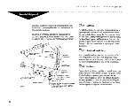
Страница 26: ...26 ij l FroxWand front and side view Unversal DB 15 to 4 BNC video connector INSTALLATION GUIDE Hardware IR emitter BNC female to female connector...

Страница 27: ...om plate of the FroxWand This exposes two openings inside the shaft of the FroxWand One is marked negative and the other is marked positive o 3 Place two batteries with negative side up in the opening...

Страница 28: ...he respective boxes Use a pencil INSTALLATION GUIDE Hardware when writing down which components are connected to each port As stated on page one these charts will be a useful tool when entering the So...

Страница 29: ...ONNECTING THE MEDIA PROCESSOR WITH THE VIDEO PREPROCESSOR o 1 Connect one end of the SCSI cable provided in the AAP 01 Frox Accessory Kit to the Media Processor Digital Video In port and the other end...

Страница 30: ...INSTALLATION GUIDE Hardware INSTALLER S NOTES 30...

Страница 31: ...e sure to install the audio video device needed to be active under every circumstance in the VCRI In port The alternate monitor feature sends video to a television through the S video and or composite...

Страница 32: ...e Ground INSTALLATION GUIDE Hardware Signal Timing Pixel Clock 28 636363 MHz Horizontal Frequency Horizontal Period Horizontal Active Scan Horizontal Blanking Horizontal Front Porch Horizontal Sync Pe...

Страница 33: ...y scale and color balance using reference test patterns and signals typically derived from test pattern generators or reference videotapes or laserdiscs While this is fine for analog systems it is not...

Страница 34: ...rox images SYNCHRONIZATION ISSUES WITII DATAGRADE MONITORS Datagrade monitors input analog video signals broken down into separate red green blue and synchronization sync components The sync component...

Страница 35: ...he Media Processor than the provided cable allows This will require that each of the red green blue and sync leads be extended using coaxial cable Remember that when running video via coaxial cable on...

Страница 36: ...of a high quality S video or com posite video cable to the appropriate Laserdisc VCR2 output of the Video Preprocessor o 3 Connect the other end of the cable to the desired S video or composite video...

Страница 37: ...tem be sure that a Signal strength of at least 7dB is available at the Video Preprocessor RF input Ideally the FroxSystem would like to see lOdB at the Video Preproces sor RF input Passive RF signal...

Страница 38: ...h FroxSystems Use top quality audio and video cables gold plated connectors etc These cables can vastly improve audio and video performance in properly wired installations Cheap INSTALLATION GUIDE Har...

Страница 39: ...V signal to the Video Preprocessor Antenna port If a cable decoder is used for this input connect the cable carrying the TV signal to the RF input on the decoder first and then run a second cable from...

Страница 40: ...INSTALLATION GUIDE Hardware INSTALLER S NOTES 40...

Страница 41: ...stallation W Amaximum of 4 CD players including analog CD players digital CD players and FroxCD Changers may be Installed per FroxSystem Installation INSTALLING A FROX CD CHANGER CDC OI D l Connect on...

Страница 42: ...coaxial wire is used connect the wire to either the Digital Audio In ports 1 or 5 If a fiberoptic cable is used connect the cable to the Digital Audio In ports 2 3 4 6 7 or 8 o 3 Connect the manufact...

Страница 43: ...when using a VCR with the FroxSystem use a model that has a built in digital time base corrector These models typically cost more than the average VCR but will ultimately provide better signals to the...

Страница 44: ...h quality video cable to the corresponding video output on the time base corrector o 4 Connect the other end of the cable to the desired video input on the Video Preprocessor INSTALLATION GUIDE Hardwa...

Страница 45: ...the RF input on the Video Preprocessor if cable decoders are being used always dedicate a cable decoder to a single RF input Never split the output from a cable decoder to more than one RF input If de...

Страница 46: ...gh quality S video or composite video cable to the desired video output of the VCR o 2 Connect the other end of the cable to the VCRI or Laserdisc VCR2 S video or composite video input on the Video Pr...

Страница 47: ...RF input on the VCR If a cable decoder is required for viewing a particular channel and that channel is desired for recording insure that a decoder is in the path of the television signal that enters...

Страница 48: ...INSTALLATION GUIDE Hardware INSTALLER S NOTES 48...

Страница 49: ...og and digital outputs of the laserdisc player to the FroxSystem When a laserdisc player is installed and a digital audio input is assigned a DIGITAL ANALOG toggle button will appear on the Laserdisc...

Страница 50: ...G LASERDISC PLAYER VIDEO CR1 V L R In outl 1 S Video 1 S Video2 In Out In Out o 1 Connect one end of a high quality S video or composite video cable to desired video output of the laserdisc player o 2...

Страница 51: ...figuration on the supplied back panel charts by mapping each speaker to a physical output port on either the Media Processor or the Video Preprocessor noting which audio channel the speaker is suppose...

Страница 52: ...Hardware which then connects to a D A converter the D A converter analog output labeled left would carry channell and the output labeled right would carry channel 2 AUDIO AMPUFIERS AND TIlE FROXSYSTE...

Страница 53: ...Remember that the left channel output represents the first channel of the audio channel pair that will be asSigned to a FroxSystem output during the software installation of speakers o 4 Wire the corr...

Страница 54: ...ERS Digital speakers will be connected to the FroxSystem by using accessory fiberoptic cables that connect to both the speaker and the Digital Audio Out ports on the Media Processor While the rear pan...

Страница 55: ...l There are two stereo pairs of analog audio inputs on the FroxSystem s Video Preprocessor Aux In 1 Aux In 2 Aux Audio 1 L R Aux Audio 2 UC RlS When a miscellaneous analog audio component is installed...

Страница 56: ...INSTALLATION GUIDE Hardware INSTALLER S NOTES 56...

Страница 57: ...is desired in a system the FroxSystem can be configured to be device selective Installations With two Similar Components If an installation has one or more instances of two similar components the IR...

Страница 58: ...all the installation rules as defined previously in this section INSTALLATION GUIDE Hardware INSTALUNG AN IR EMITTER CABLE o 1 Connect the 1 8 male mini phono end of the IR Emitter Cable provided in...

Страница 59: ...ts on the Media Processor s rear panel These inputs are compat ible with most third party IR repeaters They can be connected via the Frox FCI OO1 interface cable available from Frox and Videolink Alte...

Страница 60: ...ccur even if the sensor being contaminated is not the one currently being used to input FroxWand commands i e one located in another room zone The effects of noise and or interfer ence are additive wi...

Страница 61: ...ters that plug into the Device ports located on the back of the Media Processor see the Hardware Installation section Connecting IR Repeaters to review how the FroxSystem treats zones X lO commands wi...

Страница 62: ...routing platform in addition to the system s primary home theater role INSTALLATION GUIDE Hardware Separate FroxZone hardware and software installation documentation is available from Frox Contact th...

Страница 63: ...ing the PWR button on the FroxWand Hard power cycling the FroxSystem can take up to 30 seconds before full functionality is available During the course of a hard power cycle the front LED Frox triangl...

Страница 64: ...ighting false command triggers can occur This includes some IR commands from other manufacturer s IR remote controls There are three Wand Sensitivity settings Low Mid and High The Low setting will att...

Страница 65: ...the WAND SPEED button o 2 Click on the SLOW MID or FAST button under Speed as desired TO SELECT A WAND SENSITIVITY o 1 Click on the WAND SPEED button o 2 Click on the LOW MID or HIGH button under Sens...

Страница 66: ...he FroxSystem Software Installation procedure o 1 CLICK ON the FROX button o 2 Scroll down to the second menu page INSTALLATION GUIDE Software o 3 CLICK ON the INSTALLATION option 0 PIP Mono Volume Q...

Страница 67: ...4 5 6 IFrail CD Player 7 8 9 0 Space Clear Del IEnter I I Set Install Password I Enter Authorization Code I Locale II Analog Audia Video II TV Channels II Next II Done I ISpeakers II Digital Audio It...

Страница 68: ...allation password and click on the ENTER button Upon re entering iNSTALLATION the system will wait for the entry of this installation password The data entry box will now read Enter InstallPassword Al...

Страница 69: ...Haven Boston Provlden e Albany New York Metro Penn N y lo ale Fri May 28 1993 1 30 27 pm o 1 Click on the market area in the scroll menu that best describes Your IV Market Area 1 21JAnalog Audio Video...

Страница 70: ...INSTALLATION GUIDE Software INSTALLER S NOTES 70...

Страница 71: ...Installation Control Stripe The TV Channels installation section is used to assign the proper FroxCast Data Channel configure a cable modulation channel and assign channel numbers to local and nation...

Страница 72: ...in your area If you are unsure as to which FroxCast data carrier is available in your area chose one from this chart Please use a national FroxCast Data Carrier Region VBI Line WTBS National 20 WGN Na...

Страница 73: ...channel number is only a single digit then the ENTER button must be selected ASSIGNING CHANNEL NUMBERS TO LOCAL AND NATIONAL STATIONS o 1 Click on the NATIONAL channels button below the stations list...

Страница 74: ...INSTALLATION GUIDE Software INSTALLER S NOTES 74...

Страница 75: ...ble or antenna path prior to entering any RF input I i When installing the RF tuner inputs on VCRs or the RF input on the Video Preprocessor always dedicate a cable decoder to a single RF input Never...

Страница 76: ...equipment INSTALLING TV SIGNALS Instructions for installing TV signals to VCR RF inputs are described below and is repeated under the section regarding VCRs o 1 Using the NEXT and PREY buttons on the...

Страница 77: ...Make and Model IVCtt 1lJ VC Jerrold 400 old4SQ __ VCR Tuner In 1Cable ith Decode rtll RC5S0 Oak RCU400 c Always Use Alternate Monitor J Learn o 3 If a Cable with Decoder is selected click on the appr...

Страница 78: ...INSTALLATION GUIDE Software INSTALLER S NOTES 78...

Страница 79: ...Alternate Monitor I B i 9 V J TV Channels I Next I Done Avideo device such as a VCR or laserdisc player must be installed in Video Speakers I Digital Audio thorizationI Prev I Maintenance I In 1 befo...

Страница 80: ...CR from S video In o 3 From the list of devices click on the Device Make and Model for the VCR in question If the particular model number for a manufacturer is not listed select another model from the...

Страница 81: ...Monitor I number for your decoder is not available in the provided listings select another model from the same manufacturer It is quite probable that models from the same manufacturer use the same inf...

Страница 82: ...another model from the same manufacturer It is quite probable that models from the same manufacturer use INSTALLATION GUIDE Software the same infrared IR codes If there is no suitable chOice then the...

Страница 83: ...ns on the Installation Control Stripe scroll through the pages of installation screens to locate the desired Current Connection Video In 1 or Video In 2 o nection and Component Frox Component IVideo P...

Страница 84: ...tware and Model for the LD player in question If the particular model number for a manufacturer is not available in the prOvided listing select another model from the same manufacturer It is quite pro...

Страница 85: ...there is no subcode information available on the analog output of a CD player all data related FroxSystem features such as CD Identification and Elapsed Time Counter will not be available Only one 10...

Страница 86: ...trWSome CD players including combination CD LD players with digital outputs strip the subcode information from the digital data stream Though these components can be used to play audio through the Fr...

Страница 87: ...L c _ _ 5 t _35_ __ J Current Connection I DIgitalIn 1 Wired Devita M ke and Model I tCxt M1D IPhilips eND o 4 If additional digital CD players are to be installed repeat steps 1 through 3 INSTALUNG...

Страница 88: ...Model of your analog CD player If the particular model number is not available in the device list select another model from the same manufacturer It is quite probable that models from the same manufa...

Страница 89: ...COMPONENTS To enter the miscellaneous analog audio device installation section click on the ANALOG AUDIO VIDEO button located on the Installation Control Stripe Current Connedion Always Use Alternate...

Страница 90: ...When a miscellaneous analog audio device is installed in Aux In 1 or Aux In 2 an OTHER or OTHER 2 button will appear as options in the Audio Routing Screen Aselection of these controls will route the...

Страница 91: ...droom 4 Kitchen Den Family Room Patio Rec Room Bathroom 1 Bathroom 2 Bathroom 3 Great Room and Pool Room names can B IAnalog Audio Video I TV Channels I Next I Done Digital Audio J IAuthorization J El...

Страница 92: ...channel 2 An interactive graphical representation of the FroxSystem analog and digital audio outputs is displayed on screen to simplify the installation process INSTALLATION GUIDE Software INSTALLING...

Страница 93: ...as gray filled when the room associated with those ports in not the current room selected o 6 Click on the appropriate Center Speaker Type If any Center Surround speakers have been installed this will...

Страница 94: ...the room associated with those ports in not the current room selected If the L R SUBWOOFER button is selected the entry in the Associated Speakers browser will read Left Right Sub instead of Left Righ...

Страница 95: ...here is a button called CALIBRATION that presents a subpanel of detailed calibration controls Once the room is calibrated for optimum sound it is advised that the installer lock this menu away from al...

Страница 96: ...INSTALLATION GUIDE Software INSTALLER S NOTES 96...

Страница 97: ...ability and displays the Frox Gill with its proper graphics resolution When an alternate monitor is active all devices installed in Video In 2 will become inaccessible The alternate monitor feature fo...

Страница 98: ...alternate monitor is engaged the FroxSystem can turn the television ON or OFF via the FroxWand s F2 control INSTALLING THE ALTERNATE MONITOR FOR ON DEMAND USE o 1 USing the NEXT and PREV buttons scro...

Страница 99: ...ate Monitor o 4 If the television is not required to be powered ON and OFF when the alternate monitor is activated click on the Generic 1V option under Device Make and Model o 5 If the television is r...

Страница 100: ...INSTALLATION GUIDE Software INSTALLER S NOTES 100...

Страница 101: ...configuration Restore Setup Restore the last system configuration ISystem Update I Update system to a new software release CD Covers Read CD cover images from videotape Converge Show test patterns an...

Страница 102: ...nt version of FroxSystem software is now required Without the FroxCD execution of System Update will result in an inoperable system o 2 Click on the CONFIRM button to proceed with System Update or the...

Страница 103: ...ps to correct this First turn off the Automatic Digital Tracking feature com monly found on VCRs consult the VCR s user s manual With the VCR now in a Manual Tracking mode adjust the tracking until th...

Страница 104: ...nitor calibration verses external patterns generated by a laserdisc or test pattern generator There are three test patterns provided for calibrating monitors The Cross Hatch Gray Scale and SMPTE Color...

Страница 105: ...a single monitor in a system insure that the screen positioning is at a happy medium for all monitors Be aware that the user interface shifting will affect all monitors in the system To move the User...

Страница 106: ...ceived by the system the second is the number of bad packets received Upon exiting this screen both numbers will be reset to zero The FroxCast Data Channel and VBI tine must be installed before any re...

Страница 107: ...sekeeping Time button LATE NIGHT or EARLY AFTERNOON as desired OTIlER STATISTICS INFORMATION Every FroxSystem Media Processor has its own chassis Serial Number This number is displayed on the screen a...

Страница 108: ...INSTALLATION GUIDE Maintenance INSTALLER S NOTES 108...

Страница 109: ...ng the SATURATION level Symptom The video looks washed out even though the video processingparameters are pushed high Possible causes The monitor is not set up to work properly with the FroxSystem Rea...

Страница 110: ...ome other problem Check the installation of the component and speakers Symptom When attempting to route a new audio source to a room or when selecting an audioprocessing option an informationalpop up...

Страница 111: ...the Video Preprocessor is plugged into the switched outlets of the Media Processor If so remove and reconnect the AC power directly to a source outlet There may be a bad or missing connection between...

Страница 112: ...uses Check to see if the FroxCast Data Channel is installed properly along with the VBI Line Number_ Remember the FroxSystem will only receive FroxCast data when the system is soft powered OFF_ Is the...

Страница 113: ...should be removed from the work area o All work areas should be conductive bench tops or covered by conductive mats properly connected to earth ground o The installer and the FroxSystem should be grou...

Страница 114: ...in which the Media Processor and Video Preprocessor are plugged INSTALLATION GUIDE Appendix B o 2 Remove the three screws that hold down the lid of the Media Processor These screws are found on the u...

Страница 115: ...INSTALLATION GUIDE Appendix B WAAI l I 5 115...

Страница 116: ...er supply UPS or surge protector in which the Media Processor and Video Preprocessor are plugged o 2 Remove the three screws that secure the lid of the Media Processor These screws are found on the up...

Страница 117: ...from a remote control do not hit the keys in rapid succession This will allow the FroxSystem to properly isolate and receive each command TIlE MEANING OF FROXWAND CUCKS During the course of a Learn sc...

Страница 118: ...he current position When the disc is paused and the PLAY key is pressed does the disc resume playing from the current position INSTALLATION GUIDE Appendix D Please press FORWARD SCAN BACKWARD SCAN FOR...

Страница 119: ...ing from a new chapter CABLE DECODER LEARN MODE SCRIPT When learning to control the Cable Box the FroxSystem will ask you to perform a sequence of operations on the Cable Box remote control while you...

Страница 120: ...LATION GUIDE Appendix D activation trigger on the FroxWand Please turn off the light during the learning process To continue select the PROCEED button and CLICK ON the FroxWand Please type the manufac...

Страница 121: ...st CLICK ON the FroxWand instead of that key Please select the number that describes the behavior of the CD player when the last track of a CD is playing and the NEXT TRACK key is pressed 1 Stays on t...

Страница 122: ...DIGITAL output INSTALLATION GUIDE Appendix D VCR LEARN SCRIPT When learning to control the VCR the FroxSystem will ask you to perform a sequence of operations on the VCR remote control while you point...

Страница 123: ...IlCK ON the FroxWand Assuming the VCR is ready for FORWARD SCAN please press the keystroke s to start the slowest FORWARD SCAN and step to the fastest You may have to press the same key more than once...

Страница 124: ...Assuming the VCR is in slowest SLOW MOTION PLAY please press the keystroke s to step to the fastest You may have to press the same key more than once Please refer to the Operations Manual for assistan...

Страница 125: ...d of that key Please press numbers 0 20 sequentially and 0 20 sequentially once again Please DO NOT press the number 20 key instead of the number 20 key If any key for example 20 does not exist CLICK...

Страница 126: ...INSTALLER S NOTES 126...

Отзывы: