


5
EN
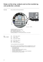
Choice of location
Proper use
The solar inverter is intended exclusively to convert direct current from solar modules into
alternating current and to feed this into the public grid.
The inverter is only designed to be used with non-grounded solar modules.
Improper use comprises:
-
utilisation for any other purpose or in any other manner
-
making any modifications to the inverter that have not been expressly approved by
Fronius
-
the installation of components that are not distributed or expressly approved by Froni-
us.
Fronius shall not be liable for any damage resulting from such action.
No warranty claims will be entertained.
Proper use also includes:
-
carefully reading and obeying all the instructions and all the safety and danger notices
in the operating instructions
-
performing all stipulated inspection and maintenance work
-
installation as specified in the operating instructions.
When designing the photovoltaic system, ensure that all of its components are operated
within their permitted operating ranges at all times.
Observe all the measures recommended by the solar module manufacturer to ensure long-
term retention of the solar module's properties.
Obey the regulations of the energy supply company regarding feeding energy into the grid.
General com-
ments regarding
choice of location
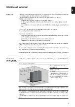
The following criteria should be taken into account when choosing a location for the invert-
er:
Install only on a solid surface
Max. ambient temperatures:
-25°C/+45°C
Relative humidity:
0 - 100%
The airflow within the inverter is
from the top to the rear (cold air
taken in from above, hot air dissi-
pated out of the rear).
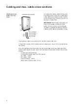
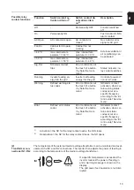
If the inverter is installed in a switch cabinet or a similar sealed area, then forced-air ven-
tilation must be provided to ensure adequate heat dissipation.
If the inverter is to be installed on the outer wall of a cattle shed, maintain a minimum all-
round clearance of 2 m between the inverter and all ventilation and other openings in the
building.
The installation location must not be exposed to ammonia, corrosive vapours, salts or ac-
ids.
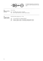
1,2 m
(47.2 in.)
0,3 m
(11.8 in.)
0
1,2 m
(47.2 in.)
0
-25 °C - +50 °C
(-13 °F - +122 °F)
0 - 100 %