


9
EN
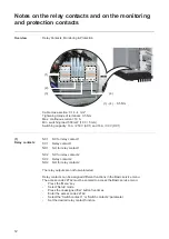
Notes regarding DC connection
General com-
ments regarding
solar modules
To enable suitable solar modules to be chosen and to use the inverter as efficiently as pos-
sible, it is important to bear the following points in mind:
-
If insolation is constant and the temperature is falling, the open circuit voltage of the
solar modules will increase. The open circuit voltage must not exceed 950 V.
If the open circuit voltage exceeds 950 V, the inverter will be destroyed and no war-
ranty claims will be entertained.
-
More exact values for dimensioning the solar modules can be provided by suitable cal-
culation programs, like the Fronius Solar.configurator (which can be downloaded from
www.fronius.com).
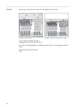
DC connection
area
The DC connection area is located on the
lower area at the front of the inverter.
The DC cable is connected via a V-type ter-
minal or alternatively using an M12 cable
lug.
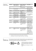
IMPORTANT!
Only the following cables
may be connected to V-type terminals:
-
RE (round single-wire)
-
RM (round multi-strand)
-
SE (sector-shaped single-wire)
-
SM (sector-shaped multi-strand)
-
Fine-core cables, in conjunction with
ferrules only
When connecting the DC cable using an
M12 cable lug, fine-core cables are permit-
ted.
Connecting alu-
minium cables
Aluminium cables can also be connected to the DC connections.
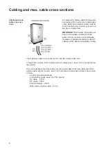
Max. cross-sec-
tion of DC cables
When cabling from below, the max. cable cross-section of DC cables is 240 mm².
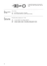
NOTE!
Before connecting up the solar modules, check that the voltage for the so-
lar modules specified by the manufacturer corresponds to the actual measured
voltage.
NOTE!
After removing the lower
cover, unplug the grounding cable
from the cover.
NOTE!
When connecting aluminium cables:
-
observe national and international guidelines regarding the connection of al-
uminium cables
-
follow the instructions of the cable manufacturer
-
Once a year, make sure that the cables are securely connected according to
the specified torque.