background image

1

30" (762 mm) ELECTRIC RANGE INSTALLATION INSTRUCTIONS

(For 4 Wire, 60 Hz. Systems)

INSTALLATION AND SERVICE MUST BE PERFORMED BY A QUALIFIED INSTALLER.

IMPORTANT: SAVE FOR LOCAL ELECTRICAL INSPECTOR'S USE.

READ AND SAVE THESE INSTRUCTIONS FOR FUTURE REFERENCE.

P/N  316259203 REV C (1409)

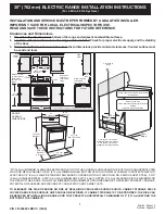
Clearances and Dimensions

1.  Provide adequate clearances between the range and adjacent combustible surfaces.

2.  Location—Check location where the range will be installed. Check for proper electrical supply, and the stability 

of the floor.

3.  Dimensions that are shown must be used. Given dimensions provide minimum clearance. Contact surface must 

be solid and level.

*30" (762 mm) MINIMUM CLEARANCE BETWEEN THE TOP OF THE COOKING SURFACE AND THE  BOTTOM OF AN UNPROTECTED 

WOOD OR METAL CABINET; OR 24" (610 mm) MINIMUM WHEN BOTTOM OF WOOD OR METAL CABINET IS PROTECTED BY NOT 

LESS THAN 1/4" (6 mm) FLAME RETARDANT MILLBOARD COVERED WITH NOT LESS THAN NO. 28 MSG SHEET STEEL, 0.015" 

(0.4 mm) STAINLESS STEEL, 0.024" (0.6 mm) ALUMINUM OR 0.020" (0.5 mm) COPPER. 0" (0 mm) CLEARANCE IS THE MINIMUM FOR 

THE REAR OF THE RANGE. FOLLOW ALL DIMENSION REQUIREMENTS PROVIDED ABOVE TO PREVENT PROPERTY DAMAGE, 

POTENTIAL FIRE HAZARD, AND INCORRECT COUNTERTOP AND CABINET CUTS.

TO ELIMINATE THE RISK OF BURNS OR FIRE BY REACHING OVER HEATED SURFACE UNITS, CABINET STORAGE SPACE 

LOCATED ABOVE THE SURFACE UNITS SHOULD BE AVOIDED. IF CABINET STORAGE IS TO BE PROVIDED, THE RISK CAN 

BE REDUCED BY INSTALLING A RANGE HOOD THAT PROJECTS HORIZONTALLY A MINIMUM OF 5" (127 mm) BEYOND THE 

BOTTOM OF THE CABINETS.

English - Pages 1-4

Français - Pages 5-8

FRONT 

VIEW

Minimum to wall 

on either side of 

range above 

36’’ (914 mm) 

height.

SIDE

VIEW

1”

(25 mm)

36”

(914 mm)

30” 

(762 mm)

Minimum

30” 

(762 mm)

18”

(457 mm)

Minimum to 

cabinets on 

either side of 

range.

13”

330 mm

Maximum depth 

for cabinets 

above range top.

0” (0 mm) clearance below cooking top and at rear of range.

30”

(762 mm)

RANGE

OVERALL

DIMENSIONS

30”

(762 mm)

25- 3/4”

(654 mm)

48”

(1219 mm)

Maximum

49”

(1245 mm)

Maximum

Door Open

29- 7/8”

(759 mm)

36


1/8”

Centerline of 

range

All dimensions for electrical outlet location 

are maximum.

Dashed cubed area

 shows where the electrical outlet must be 

installed

 for flush to the wall installation.

25”

635 mm

11”

(279 mm)

22”

(559 mm)

Wall 

Edge

2-5/8” (67 mm) for models 

equipped with warmer drawers

3-1/2” (89 mm) for models 

equipped with storage drawers

6”

(152 mm) 

(3 mm)

(940 mm)

Содержание CGLEF379GC

Страница 1: ...LOW ALL DIMENSION REQUIREMENTS PROVIDED ABOVE TO PREVENT PROPERTY DAMAGE POTENTIAL FIRE HAZARD AND INCORRECT COUNTERTOP AND CABINET CUTS TO ELIMINATE THE RISK OF BURNS OR FIRE BY REACHING OVER HEATED SURFACE UNITS CABINET STORAGE SPACE LOCATED ABOVE THE SURFACE UNITS SHOULD BE AVOIDED IF CABINET STORAGE IS TO BE PROVIDED THE RISK CAN BE REDUCED BY INSTALLING A RANGE HOOD THAT PROJECTS HORIZONTALLY...

Страница 2: ...driver or Flat Head Screwdriver Electric Drill 1 8 3 mm Diameter Drill Bit Masonry Drill Bit if installing in concrete For electrical supply connection 1 4 6 mm 3 8 10 mm Socket driver or Nutdriver Additional Materials You May Need CopperElectricalWiring MetalConduit forhardwiring Normal Installation Steps 1 Anti Tip Bracket Installation Instructions Important Safety Warning To reduce the risk of ...

Страница 3: ...y removing lower panel or storage drawer For models with a warmer drawer or broiler compartment grasp the top rear edge of the range and carefully attempt to tilt it forward 2 Electrical Connection Requirements Avoid fire hazard or electrical shock Failure to follow this warning may casue serious injury fire or death Plug the range power cable 4 conductors into a 4 conductor range outlet Outlet mu...

Страница 4: ...ntenance disconnecttheelectricalpowersupply Iftheelectricalsupplyis inaccessible lift the unit slightly at the front and pull out away from the wall Pull only as far as necessary to disconnect the electrical supply Finish removing the unit for servicing and cleaning Reinstall in reverse order making sure to level the range and check electrical connections See pages 2 and 3 for proper anchoring ins...

Страница 5: ...S CI DESSUS AFIN D ÉVITER LES DOMMAGES À LA PROPRIÉTÉ LES RISQUES D INCENDIE AINSI QUE DES COUPES ERRONÉES D ARMOIRES ET DE DESSUS DE COMPTOIR DES ARMOIRES D ESPACE DE RANGEMENT SITUÉES AU DESSUS DES UNITÉS DE SURFACE DEVRAIENT ÊTRE ÉVITÉES AFIN D ÉLIMINER LES RISQUES DE BRÛLURES OU D INCENDIE EN TENDANT LA MAIN PAR DESSUS LES UNITÉS DE SURFACE CHAUDES LE RISQUE PEUT ÊTRE RÉDUIT EN INSTALLANT UNE ...

Страница 6: ...ou par la cuisinière elle même Lesupportdecontre renversementdoitaussiêtredéplacéetinstallé avec la cuisinière si celle ci est relocalisée Des instructions sont fournies pour une installation sur du bois ou du ciment fixée soit au plancher ou au mur Assurez vous que les vis pénètrent complètement la cloison du mur et qu elles sont bien ancrées dans le bois ou le métal lorsque l installation est fa...

Страница 7: ...ment en retirant le panneau inférieur ou le tiroir de rangement Saisissez la partie supérieure arrière de la cuisinière et essayez prudemment de la faire basculer vers l avant pour les modèles possédant un tiroir réchaud ou une rôtisserie 32 mm 32 mm 2 Exigences du raccordement électrique Évitez tout risque d incendie ou de choc électrique Nepassuivrecetavertissementpeutcauserdesblessures graves u...

Страница 8: ...tettirezafin de l éloigner du mur si l accès à l alimentation électrique est inaccessible N éloignezdumurquedeladistancenécessaire pour débrancher l alimentation électrique Finissez de déplacerl appareilpourl entretienetlenettoyage Réinstallez en ordre inverse en vous assurant de mettre la cuisinière à niveau et vérifiez les raccordements électriques Voyez les pages 2 et 3 pour les instructions co...

Отзывы: