


119
PB
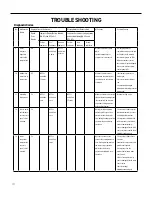
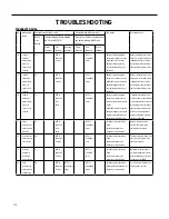
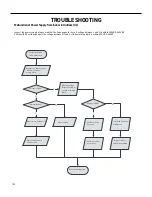
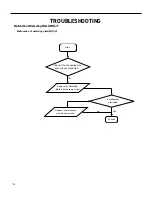
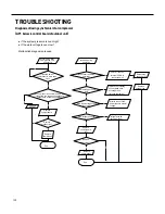
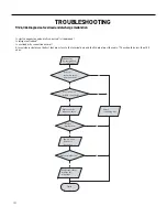
TROUBLESHOOTING
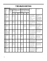
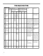
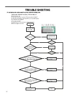
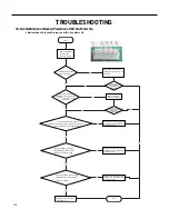
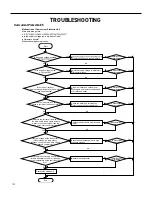
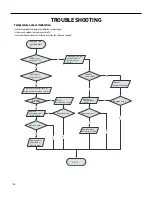
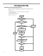
9-12k Malfunction of blocked Protection of IDU Fan Motor H6
End
No
Yes
No
Yes
No
Yes
Connect power and restart the unit.
Test whether the voltage between terminal 1 and terminal 2
of motor interface is within 280~310VDC.
Yes
No
No
No
Yes
Then check whether there is voltage
between terminal 2 and terminal 4
of the motor interface.
Yes
Yes
No
Whether the fan blades
can run smoothly?
Turn the fan blades
by hand under
power-off condition
Adjust the motor and blade
assembly so that rotor can run
smoothly.
Under power-off condition,
check whether the wiring terminal
between indoor fan and main
board is loose.
Turn unit on
to check whether the
malfunction is
eliminated.
Turn unit on
to check whether the
malfunction is
eliminated.
Reinsert the wiring
terminal of indoor fan.
It's the malfunction of main board.
Replace a new main board that is
of the same model.
It's the malfunction of main board.
Replace a new main board that is
of the same model.
It's the malfunction of main board.
Replace a new main board that is
of the same model.
Then check whether the voltage
between terminal 2 and terminal 3
of the motor interface is 15VDC.
It's the malfunction of motor.
Replace a new motor that is
of the same model.
Start
2. Malfunction of Blocked Protection of IDU Fan Motor H6
Main detection points:
●
SmoothlyIs the control terminal of PG motor connected tightly?
●
SmoothlyIs the feedback interface of PG motor connected tightly?
●
The fan motor cant operate?
●
The motor is broken?
Malfunction diagnosis process:
Содержание FSHW091
Страница 8: ...8 INTRODUCTION FSHSW09A1A FSHSW12A1A Figure 102 Indoor Units FSHSW18A3A FSHSW24A3A FSHSW36A3A ...
Страница 47: ...47 INSTALLATION ...
Страница 48: ...48 INSTALLATION Installation Tools ...
Страница 72: ...72 WIRED CONTROLLER Display ...
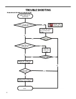
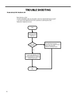
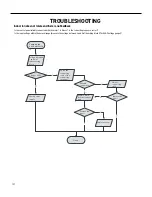
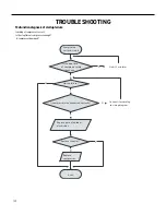
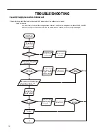
Страница 122: ...122 TROUBLESHOOTING Malfunction of IDUFanMotorU8 Service Manual No Start End ...
Страница 146: ...146 WIRING DIAGRAMS Figure 8054 9 12KOutdoorUnitWiringDiagrams 60000706067401 3 2 N 1 C3 C4 ...
Страница 147: ...147 WIRING DIAGRAMS Figure 805 18 24kOutdoorUnitWiringDiagrams Figure 806 36kOutdoorUnitWiringDiagrams 6361000047001 ...
Страница 158: ...158 FIgure 906 PARTS CATALOG 9KOutdoorUnit 28 27 29 31 30 32 ...
Страница 160: ...160 PARTS CATALOG 12k OutdoorUnit 28 27 29 31 30 32 FIgure 907 ...


