


VYPER
™
VARIABLE SPEED DRIVE
OPERATION
100-200 IOM (FEB 09)
Page 41
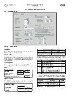
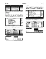
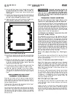
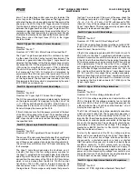
VFD and Capacity Control Settings
This section of the motor page provides programmable pa-
rameters which regulate the loading and unloading response
of the Vyper
™
drive. Both the Slide Valve and the Speed limits
of the motor control are set on this page. There are various
control strategies which are unique to specific industries.
The following pages will show some suggestions that can
be used as starting points. Specific applications may require
further refinements.
VFD
Maximum Drive Output
%
Minimum Drive Output
%
Delay
Rate of Increase
%
5 SEC
Rate of Decrease
%
5 SEC
Setting the Motor Screen VFD Parameters -
Setting the
MOTOR screen properly is critical to the optimal desired
performance of the Vyper
™
.
It is important to understand how the MOTOR screen param-
eters affect the functionality of the Vyper
™
unit. The param-
eters affect the reaction speed of the VSD when accelerating
and decelerating and also affect the interaction between the
motor speed and the slide valve.
Maximum Drive Output Speed -
This parameter sets the limit
for the highest allowable motor speed in terms of percentage.
The maximum allowable setting is 100% or full speed. In some
situations an application may require the maximum motor
speed to be limited. The Maximum Percentage parameter
range can be set from 0 to 100%. However, it is recommended
that the Maximum percentage is always set to a higher value
than the Minimum Percentage parameter setting.
Minimum Drive Output Speed -
This parameter sets the
lowest allowable percentage of motor speed at which the
Vyper
™
will permit the motor to run for an indeterminate pe-
riod. The range on this function is 20 to 100%. The value of
this parameter must always be set lower than the Maximum
Percentage setting. The value of this setting is very critical,
as many electric motors are not designed for low speed op-
eration due to temperature and lubrication requirements. It is
highly recommended that the manufacturer of the motor is
contacted to determine if the design can be safely operated at
the intended minimum speed. This parameter should never be
set lower than the minimum allowable motor speed as recom-
mended by the supplier. Settings of this parameter which are
lower than the supplier recommended minimum percentage
speed may result in severe damage or loss of the motor.
Rate of Increase -
The Rate of Increase parameter setting
determines the speed change step size at which the Vyper
™
will accelerate the motor. The Rate of Change setting works in
conjunction with the Cycle Time setting to provide variability in
the desired speed change step rate. The Vyper
™
has an inter-
nally set rate of acceleration of 6.08 Hz/sec. At setting values
lower than 10%, a dwell time appears between acceleration
steps due to an interaction between Vyper
™
communications
frequency, the Rate of Change and Cycle Time settings, and
the maximum acceleration rate of 6.08 Hz/sec.
Rate of Decrease -
The Rate of Decrease parameter set-
ting determines the speed change step size at which the
Vyper
™
will decelerate the motor. The Rate of Decrease
setting works in conjunction with the Cycle Time setting to
provide variability in the desired speed change step rate. The
Vyper
™
has an internally set rate of deceleration of 6.08 Hz/
sec. At setting values lower than 10%, a dwell time appears
between deceleration steps due to an interaction between
Vyper
™
communications frequency, the Rate of Change and
Cycle Time settings and the maximum acceleration rate of
6.08 Hz/sec.
Rate of Increase Delay Time -
The Rate of Increase Delay
Time setting is used in conjunction with the Rate of Increase
setting to determine the acceleration response of the VSD
acceleration rate step.
Rate of Decrease Delay Time -
The Rate of Decrease Delay
Time setting is used in conjunction with the Rate of Decrease
setting to determine the deceleration response of the VSD
acceleration rate step.
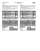
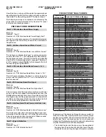
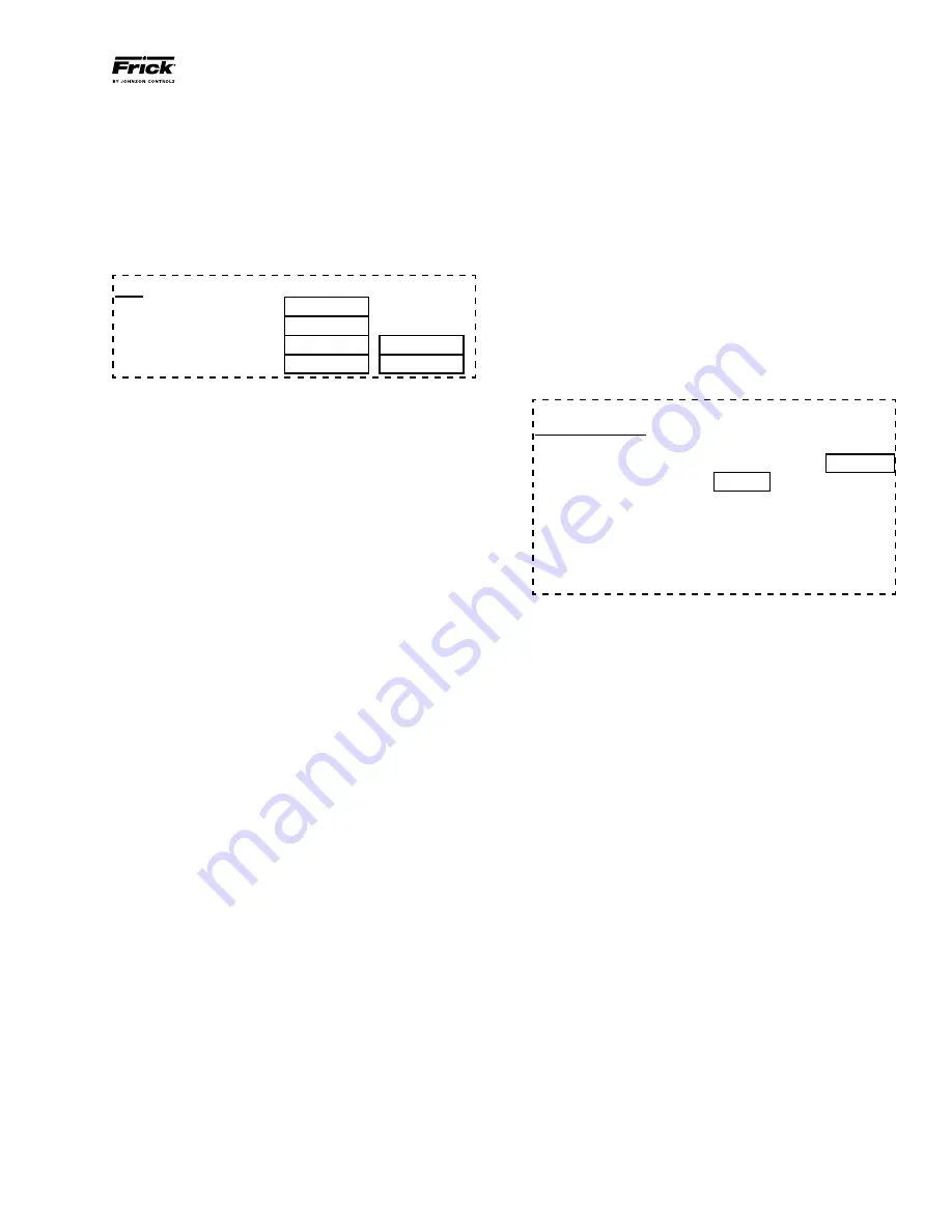
Capacity Control Settings
Capacity Control
The Drive Speed will increase and decrease proportionally
with the Slide Valve* until the Slide Valve* reaches
%
and the Drive Speed reaches
%
Above these setpoints, the Drive Speed will be controlled
by the Rate Of Increase and Decrease while the
Slide Valve* will operate independently.
*Slide Valve or other mechanical unloader
Variable Speed Minimum Slide Valve Position
40.0%
NOTE: Slide Valve Range limited to protect compressor
Proportional Slide Valve Setpoint -
This parameter sets
the maximum slide valve percentage at which the Vyper
™
operates under proportional capacity control in conjunction
with speed change. Proportional control exists between this
setpoint and the minimum slide valve position. This value
must always be set less than 100%.
Proportional Speed Setpoint -
This setpoint represents the
maximum percentage of speed while under proportional con-
trol when used in conjunction with the slide valve. At speeds
higher than this setpoint, the capacity is under total speed con-
trol. At values between this setpoint and the minimum speed
setpoint, the compressor is under proportional control.
Minimum Slide Valve Position -
This setting establishes the
minimum Slide Valve position possible while the Frick screw
compressor is running. At Minimum Drive Speed, it is the
point at which no further mechanical unloading is allowed.
This setpoint is programmed as a function of the chosen mini-
mum drive speed. It is adjustable to higher minimum values
but no lower than the default minimum. The default minimum
is factory set to 40% and is not user programmable.
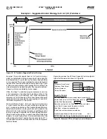
Suggested VFD and Capacity Control Settings
There are individual control strategies required for various
industries. The Vyper
™
VFD and Capacity control settings
provide versatility in meeting these individual needs. The
following pages show some suggested control strategies and
settings for individual industries. These are only suggestions.
Specific applications may require further refinements of the
control strategy.
Содержание Vyper 254
Страница 17: ...VYPER VARIABLE SPEED DRIVE INSTALLATION 100 200 IOM FEB 09 Page 17 Liquid Cooled Vyper P I Diagram Economized...
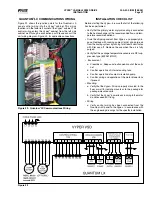
Страница 26: ...VYPER VARIABLE SPEED DRIVE INSTALLATION 100 200 IOM FEB 09 Page 26 ANALOG BOARD WIRING Figure 21...
Страница 67: ...100 200 IOM FEB 09 Page 67 VYPER VARIABLE SPEED DRIVE NOTES...