


VYPER
™
VARIABLE SPEED DRIVE
OPERATION
100-200 IOM (FEB 09)
Page 36
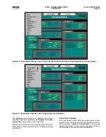
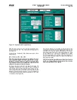
PROGRAMMING
Verify that the Vyper
™
is set to Quantum
™
LX control. This can
be accessed with the following keystrokes.
Press:
[Configuration
→
Compressor
→
Configuration]
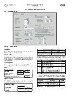
Set all dates, times, Capacity Regulations, and Package-spe-
cific information. Verify that “Screw Compressor with Vyper
™
is selected under the package Drive field. This will allow the
Vyper
™
specific screens to be displayed (See Figure 41).
VYPER
™
/ QUANTUM
™
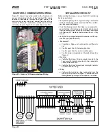
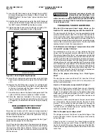
lX COMMUNICATIONS
Set the Communications rate between Vyper
™
and
Quantum
™
LX. Make sure that the Comm 1 is set as shown
in Figure 42. Press:
[Setpoints
→
Communications]
.
Figure 41 - Configuration Screen
Figure 42 - Communications Screen
Содержание Vyper 254
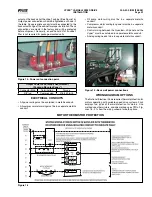
Страница 17: ...VYPER VARIABLE SPEED DRIVE INSTALLATION 100 200 IOM FEB 09 Page 17 Liquid Cooled Vyper P I Diagram Economized...
Страница 26: ...VYPER VARIABLE SPEED DRIVE INSTALLATION 100 200 IOM FEB 09 Page 26 ANALOG BOARD WIRING Figure 21...
Страница 67: ...100 200 IOM FEB 09 Page 67 VYPER VARIABLE SPEED DRIVE NOTES...