


VYPER
™
VARIABLE SPEED DRIVE
INSTALLATION
100-200 IOM (FEB 09)
Page 28
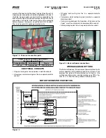
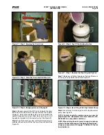
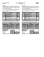
Figure 25 - Step 1, Removing the Pipe Plug
Figure 26 - Step 2, Connecting a Hose Fitting
Step 4:
Close the drain valve and refill the unit with Running
Coolant.
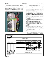
b. Verify power wiring has been connected at the correct
connection points and properly seated in accordance with
the engineering drawings for the specific installation.
c. Separate grounded metal conduits must be provided for
input power, output power, and control wiring. Failure to
provide separate conduits could result in disruption of
other electrical devices due to harmonics and REI/EMI
generated in the drive.
d. It is imperative that wiring from the drive to the motor
be enclosed in a grounded metal conduit even if poured
in a concrete floor. PVC conduit is not allowed.
e. Conduit should be bonded to the cabinet.
f. Use the conduit knockouts provided. Avoid metal shav-
ings in the drive enclosure.
g. Clean out all debris with a low power magnet or a
vacuum cleaner.
h. Protect signal wires from noise. Be sure to use shielded
and properly grounded control wires. Noisy input sig-
nals can cause erratic drive operation.
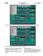
THREE INSTAllATION STEPS
Installation of the Vyper
™
can be done in a few easy steps.
Before beginning the Setup Procedures, be sure that the
cabinet has the proper electrical connections as discussed
in previous sections.
The Vyper
™
setup consists of three primary requirements:
• Cooling Loop Fluid Preparation
• Quantum
™
LX Panel Setup
• Job
FLA Trim Pot Adjustment.
COOlANT REPlACEMENT
AlWAYS WEAR EYE PROTECTION
WHEN SERVICING THE COOlING
CIRCUIT OF THE VYPER
™
.
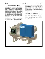
The Vyper
™
is shipped from the factory with a premixed
shipping fluid which contains a rust inhibitor that prevents
corrosion of the internal cooling passages. The shipping
fluid also helps to keep the internal passages free from
contaminants.
Shipping fluid must be drained
from cooling loop at installation of
drive and replaced with run coolant.
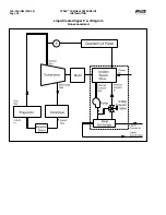
Figure 24 shows the cooling circuit of a remote-mounted wa-
ter-cooled Vyper
™
. Coolant preparation for the Glycol-cooled
version is identical. The shipping fluid must be removed
from the cooling loop and replaced with Running coolant.
To replace the shipping fluid, the following steps need to be
performed:
Step 1:
(See Figure 25) Remove the pipe plug from the top
of the exit manifold with an adjustable wrench. This allows
air to enter the system and displace the fluid during the
draining cycle.
Step 2:
(See Figure 26) Connect a hose fitting to the drain
of the heat exchanger. Be sure that the hose is connected
tightly to the drain fitting so no fluid is spilled.
Step 3:
(See Figure 27) Open the drain valve and allow the
fluid to drain from the loop. Catch buckets should be able to
hold approximately 1½ to 2 gallons of liquid.
Figure 24 - Vyper
™
Coolant Circuit
Содержание Vyper 254
Страница 17: ...VYPER VARIABLE SPEED DRIVE INSTALLATION 100 200 IOM FEB 09 Page 17 Liquid Cooled Vyper P I Diagram Economized...
Страница 26: ...VYPER VARIABLE SPEED DRIVE INSTALLATION 100 200 IOM FEB 09 Page 26 ANALOG BOARD WIRING Figure 21...
Страница 67: ...100 200 IOM FEB 09 Page 67 VYPER VARIABLE SPEED DRIVE NOTES...