


VYPER
™
VARIABLE SPEED DRIVE
INSTALLATION
100-200 IOM (FEB 09)
Page 14
between the DC link filter capacitors located on the power
unit and the logic board. This provides the means to sense
the positive, midpoint, and negative voltage connection points
of the VSD’s DC Link. Three current transformers (3T-5T)
monitor the output current from the Vyper
™
power unit and
are used to protect the motor from over-current situations.
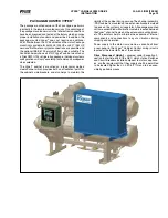
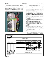
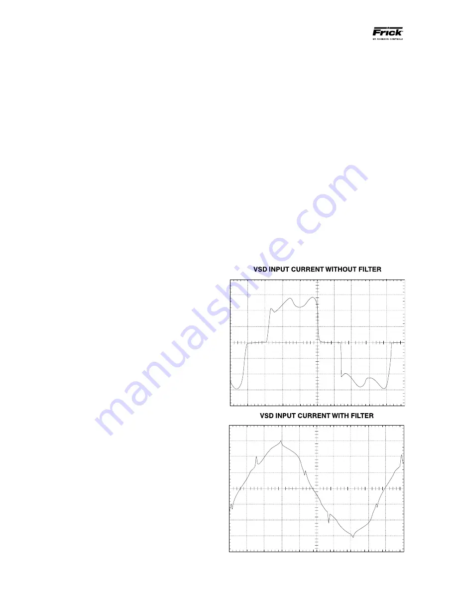
A HARMONIC FIlTER
(See Figure 8) and high frequency
trap may be added to a Vyper
™
system. The harmonic filter
is designed to meet the IEEE Std 519 -1992, “IEEE Recom-
mended Practices and Requirements for Harmonic Control
in Electrical Power Systems”. The filter is offered as a means
to “clean up” the input current waveform drawn by the Vyper
™
from the AC line, thus reducing the possibility of causing elec-
trical interference with other sensitive electronic equipment
connected to the same power source. (See Figure 8) The
Harmonic filter provides an additional benefit that corrects
the system power factor to almost unity. The Harmonic filter
should be used on all systems that require total harmonic
current distortion to be 8% or less. It is also highly recom-
mended for critical applications such as hospitals, airports,
and radar installations.
The power section of the Harmonic Filter is composed of
three major blocks:
• Precharge section,
• Three-phase inductor
• Filter Power Unit
THE FIlTER PRECHARGE SECTION
consists of three
resistors (9RES-11RES), and two contactors, precharge
contactor 1M and a supply contactor 2M. The precharge net-
work serves two purposes: to slowly charge the DC link filter
capacitors associated with the filter power unit and to provide
a means of disconnecting the filter power components from
the AC line. When the system is turned off, both contactors
are dropped out and the filter power unit is disconnected from
the AC line. When the system starts to run, the precharge
resistors are switched into the circuit via contactor 1M for a
fixed time period of 5 seconds. This permits the filter capaci-
tors in the filter power unit to slowly charge.
After the 5-second time period, the supply contactor is pulled
in, and the precharge contactor is dropped out, permitting
the filter power unit to completely charge to the peak of the
input power mains. Three power fuses (8FU-10FU) connect
the filter power components to the AC line. Very fast semi-
conductor power fuses are utilized to ensure that the IGBT
transistor module does not rupture if a failure were to occur
on the DC link of the Filter Power Unit.
THE THREE-PHASE INDUCTOR
provides some impedance for
the filter to “work against”. It effectively limits the rate of change
of current at the input to the filter to a reasonable level.
THE FIlTER POWER UNIT
is the most complicated power
component in the optional filter. Its purpose is to generate
the harmonic currents required by the Vyper
™
AC-to-DC
converter so that these harmonic currents are not drawn
from the AC line. The Filter Power Unit is identical to the
Vyper
™
Power Unit, except for two less capacitors in the filter
capacitor bank (C13-C16), a smaller IGBT module, (2MOD),
mounted to a liquid-cooled heat sink, and a Harmonic Filter
gate driver board. The Harmonic Filter Gate Driver board
provides turn on and turn off commands as determined by the
Harmonic Filter Logic board. “Bleeder” resistors are mounted
on the side of the Filter Power Unit to provide a discharge
path for the DC Link filter capacitors. In order to counteract
the parasitic inductances in the mechanical structure of the
filter power unit, the filter incorporates “laminated bus” tech-
nology and a series of small film capacitors (C23-C25). The
technology is identical to that used in the DC to AC inverter
section of the drive.
Other sensors and boards are used to convey information
back to the Filter Logic board, and provide safe operation of
the Harmonic filter. The IGBT transistor module contains a
thermistor temperature sensor (RT3) that provides tempera-
ture information back to the Harmonic Filter Logic Board via
the Harmonic Filter Gate Driver Board. This sensor protects
the Filter Power Unit from over-temperature conditions. A
Bus Isolator board is used to ensure that the DC link filter
capacitors are properly charged. Transformers DCCT1 and
DCCT2 sense the current generated by the optional filter.
These two output current sensors are used to protect the
filter against an over current or overload condition. Two input
current transformers 6T and 7T sense the input current drawn
by Vyper
™
AC to DC converter.
lINE VOlTAGE ISOlATION BOARD
provides the AC line
voltage information to the Filter Logic Board. This information
is used to determine a low bus voltage condition. The Bus
Isolation board incorporates three resistors to provide a safe
impedance between the DC Filter capacitors located on the
filter power unit and the Filter Logic board. It provides means
to sense the positive, midpoint, and negative connection
points of the filter’s DC link.
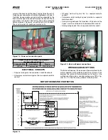
Figure 7 - Comparison of Unfiltered/Filtered Input Current
Содержание Vyper 254
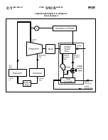
Страница 17: ...VYPER VARIABLE SPEED DRIVE INSTALLATION 100 200 IOM FEB 09 Page 17 Liquid Cooled Vyper P I Diagram Economized...
Страница 26: ...VYPER VARIABLE SPEED DRIVE INSTALLATION 100 200 IOM FEB 09 Page 26 ANALOG BOARD WIRING Figure 21...
Страница 67: ...100 200 IOM FEB 09 Page 67 VYPER VARIABLE SPEED DRIVE NOTES...