


HPS Rotary Screw Compressor Units
070.700-IOM (MAR 21)
Page 40
Maintenance
Motor and bare compressor
replacement
Refer to publication
070.660-SM
,
Bare Rotary Screw
Compressor Replacement
. Shutdown due to incorrect oil
pressure
Note:
The compressor must not operate with incorrect oil
pressure.
Refer to
Control Setup - Oil Setpoints Display
in publica-
tion
090.040-O
,
Quantum HD Control Panel.
SAE straight thread O-ring fittings
assembly procedure
When performing maintenance or replacing the compres
-
sor, you may need to remove and reinstall the hydraulic
tubing. The following procedure outlines the correct
installation of SAE straight thread fittings to SAE straight
thread ports.
The male and female ends of SAE straight thread O-ring
ports have UN/UNF straight threads. An elastomeric O-ring
is fitted to the male end. On assembly, the O-ring is firmly
sandwiched between the angular sealing surface of the
female port and the shoulder of the male end. As a result,
sealing is affected and maintained by the O-ring compres
-
sion, which results from the clamping force generated by
the tightening action. The straight threads do not offer
sealing action; they provide the resistance (holding power)
for service pressure.
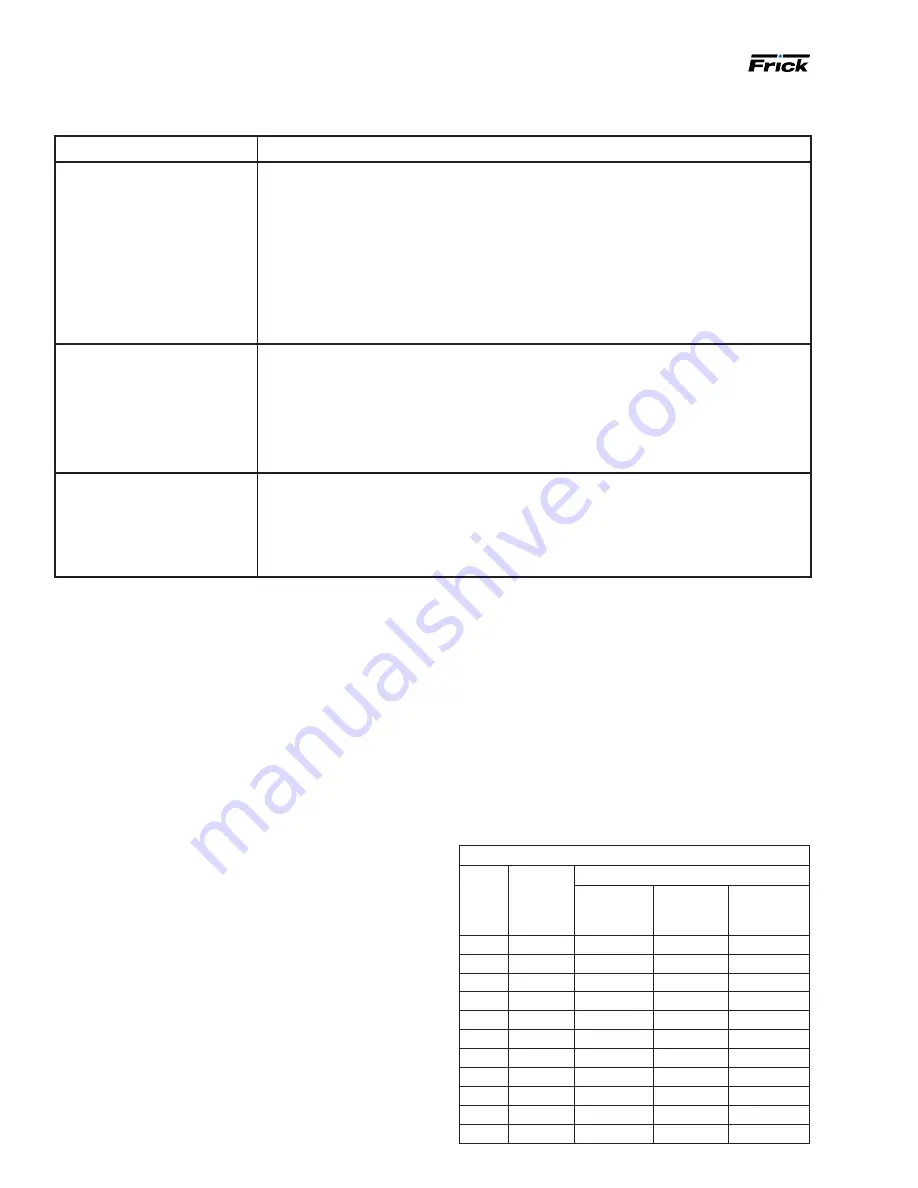
Symptom
Probable causes and corrections
High oil temperature
Insufficient liquid supply. Check receiver level. Check strainer.
Suction superheat too high. Correct system problem.
Liquid strainer blocked. Clean strainer.
Operating conditions significantly different from design.
Malfunctioning vi control solenoids. See function check of the compressor
"Volumizer ii vi control" for further detail.
Check motor valve operation and calibration.
Check calibration of analog output.
Low oil temperature
Equalizing pressure too low. Raise pressure.
Suction superheat too low or refrigerant flood back on compressor. Correct system prob
-
lem.
Operating conditions significantly different from design.
Check motor valve operation and calibration.
Check calibration of analog output.
Oil temperature
Fluctuates
System conditions rapidly fluctuate causing liquid injection system to overrespond. Stabi
-
lize
System operation.
Check calibration and operation of motor valve - adjust P and ID setpoints for analog
output.
1. Inspect components to ensure that male and female
port threads and sealing surfaces are free of burrs,
nicks and scratches, or any foreign material.
2.
If the O-ring is not pre-installed to the fitting on the
male end, install the appropriate size O-ring.
3.
Lubricate the O-ring with a light coating of system oil
or petroleum jelly.
4.
Screw the fitting into the female port until the hex flat
contacts the port face. Light wrenching may be
necessary.
5.
Tighten to the appropriate torque value shown in the
following table.
Table 15: Assembly torque
Straight and adjustable fittings or plugs (steel)
Fit-
ting
size
SAE
port
thread
size
Assembly torque
in.-lb
ft-lb
N.m
2
5/16–24
65 ± 5
5.5 ± 0.5
7.46 ± 0.68
3
3/8–24
130 ± 10
11 ± 1.0
14.9 ± 1.36
4
7/16–20
170 ± 10
14 ± 1.0
18.9 ± 1.36
5
1/2–20
260 ± 15
22 ± 1.0
29.8 ± 1.36
6
9/16–18
320 ± 20
27 ± 2.0
36.6 ± 2.71
8
3/4–16
500 ± 25
42 ± 2.0
56.9 ± 2.71
10
7/8–14
720 ± 30
60 ± 2.5
81.4 ± 3.39
12
11⁄16–12
960 ± 50
80 ± 5.0
108 ± 6.78
16
15⁄16–12
1380 ± 75
115 ± 6.0
156 ± 8.13
20
15⁄8–12
2700 ± 150 225 ± 12.0 305 ± 16.3
24
17⁄8–12
3000 ± 160 250 ± 12.0 339 ± 16.3
Troubleshooting the liquid injection oil cooling system