ADS-B FDL-DB Dual Band Series
Installation Manual
Document No. 88552 Rev A
7-58
FFS Copyright © 2020 All rights reserved.
SECTION 7
TYPICAL INTERCONNECT DIAGRAMS
7.1
Typical System Configurations
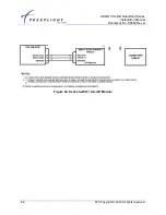
This section contains general wiring diagrams examples for popular configurations.
Air/Ground input will vary on each aircraft depending on the equipment installed. Refer to the
aircraft manual to determine the appropriate input signal to the FDL-DB Series. Light Aircraft
can refer to Section 2.5.7.1 for additional notes on Air/Ground determination.
All ports (except MPI) not connected to equipment should be set to UNUSED.
The FDL-DB Series requires an approved STC before installation
Contact FreeFlight Systems for additional information and STC validation


