


ADS-B FDL-DB Dual Band Series
Installation Manual
Document No. 88552 Rev A
2-34
FFS Copyright © 2020 All rights reserved.
2.9
Wiring Considerations
Cables with solid cores should not be used. Cables should be selected based on
the wear characteristics of their insulation material, including temperature rating,
resistance to solvents and oils, and flammability. Most inexpensive commercial
data cables have poor flammability properties.
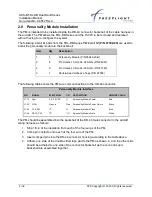
The connection from the FDL-DB-XVR Transceivers to the TC978 Controller uses a minimum of
six signal lines; the TMAP pair, the Power and Ground pair, and the Remote On discrete line
plus associated ground line. In a certified installation, MIL-W-16878E/4 or equivalent wire
should be used. Wire gauge should be 24 American Wire Gauge (AWG) for all wires. Shielded,
twisted wiring is recommended for the TMAP pair (and all serial data communication pairs) to
improve electromagnetic emissions and susceptibility
– one twist per 1 to 2 inches is adequate.
Other pairs in the bundle can also be twisted but are not required.
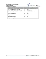
The distance between the FDL-DB-XVR Transceivers and the TC978 Controller is limited by the
impedance of the wire between them. The TC978 is powered from the transceivers, not from
aircraft power. Therefore, the acceptable voltage drop in the power line limits the wire length.
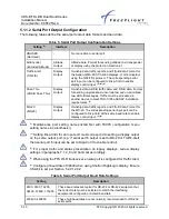
The TC978 needs an impedance of less than 1.0 ohm in the power line for satisfactory
operation. The following table gives guidelines for typical aircraft hook-up wire.
Different brands may vary
– check your supplier for details.
Gauge
Milliohm/ft
Length for 0.5 ohm
24 AWG
30.2
33.2 ft
An alternative to a harness built from individual wires, particularly for a long cable run, is to use
a multi-core cable. Aviation grade cable with six or more cores is often more expensive than the
individual wires.
2.10
UAT Antenna Installation
The UAT anten
na should be installed according to the manufacturer’s instructions.
Selecting appropriate UAT antenna locations is critical to the proper performance of the FDL-DB
Series. Consider the following when selecting the Antenna location.
•
The antennas should be well removed from any projections, the engine(s) and
propeller(s). It should also be well removed from landing gear doors, access doors or
other openings which will break the ground plane for the antenna.
•
The antenna should be mounted on the bottom and or top surface of the aircraft and in a
vertical position when the aircraft is in level flight.
•
Avoid mounting the antenna within 3 ft of the Automatic Direction Finder (ADF) sense
antenna or any Communications Receiver (COMM) antenna and 6 ft from the
transponder and Distance Measuring Equipment (DME) antennas.
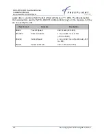
•
In installations without a digital serial interface to the transponder, the FDL-DB Series
contains a Mode A receiver to receive Mode A/C Transponder control data from the
transponder antenna through the UAT antennas. Ensure the transponder antenna is on
the bottom of the aircraft (same as the UAT antenna). The transponder antenna should