background image

Operation and Maintenance Manual, OnyX Sky Heat Recovery Units, 2022/01 


Frapol Sp. z o.o. reserves the right to introduce changes without any prior notice. 

Page

 62


8.16


Description of Installer Menu 

Confirmation of setpoints 

After changing the service settings, confirm the correct configuration of the controller to allow operation of the device


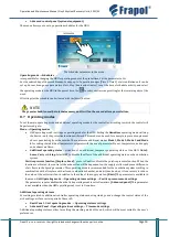
Manual control 

The menu enables manual control of individual automation components by switching them on and off. 


Basic panel 

Advanced panel (optional equipment) 

NOTE 

The controller does not check the logic protecting the components of automation system, so this menu should 
be used with caution and awareness of switching on the outputs and voltage changes made so as not to damage 
the controller and devices connected to its terminals. 

 
Filter settings 

Settings related to anti-soiling filters.  


Reset filter operation counter


 this setting is used to reset the counter of the filter working days, which will 

allow to reset the alarms warning of the need to replace the filter and start counting the filter operation days 
from scratch. 


Filter timer on/off 

 s

witching on or off the timer mechanism to inform you when filters need to be replaced.


Inspection settings 

Settings related to switching the operation of the general inspection and the HRU interlock on or off. 


Inspection  function  operation


  enable  or  disable  the  notification  about  the  necessity  to  perform  periodic 

inspection. 


Resetting work day counter 

 reset the number of working days of the unit in order to calculate the time left to 

inspection and to disable operation of the unit. 


Number of days to inspection 

 set the number of days to be notified about the necessity to perform periodic 

inspection 

 it is determined by the installer in accordance with the manufacturer's recommendations. 


Hardware configuration of HRU outputs 

The  controller  can  be  programmed  to  control  individual  outputs  of  the  HRU,  which  affects  the  control  of  devices 
connected  to  these  outputs.  The  actuators  of  the  dampers  used  should  be  controlled  on  an  ON-OFF  basis,  which 
corresponds to the position of the damper in the Open-Close position. Note: it is recommended to use a damper with an 
actuator on the inlet side which will cut off air flow when the controller is switched off. 


GHE


operation


 switching the GHE control module on or off. If the GHE is not available in the system, switch 

off the operation of the GHE by setting the parameter to 

No

, so that the operation of the regulation algorithm 

is not affected by the lack of the module. 


Reheater type 

 activate or deactivate the type of the reheater in use.


Cooler operation disable temperature 


If the temperature drops below this setting, the operation of the cooler 

will be disabled. It will be enabled when the temperature of the air intake rises above this setpoint plus the 

hysteresis of 2°C.


Primary air heater type 

 activate or deactivate the type of the 

primary air heater

 in use.


Содержание Onyx SKY 1000

Страница 1: ...on and Maintenance Manual OnyX Sky Heat Recovery Units 2022 01 Frapol Sp z o o reserves the right to introduce changes without any prior notice Page 1 OPERATION AND MAINTENANCE MANUAL for Heat Recover...

Страница 2: ...24 5 4 Air filters 24 5 5 Fan 24 5 6 Installing the controller 24 5 7 Drainage of condensate 37 5 8 Electric heater 38 6 Pre start check and starting up 40 6 1 Check 40 6 2 Start up 41 7 Operation 41...

Страница 3: ...allation in accordance with the applicable safety regulations Persons who operate means of transport a forklift truck crane etc must have appropriate qualifications When transporting the unit wear per...

Страница 4: ...g and manufacturing the equipment solutions were applied that minimise possible hazards to persons and property However this does not eliminate all possible risks Below is the list of some events outs...

Страница 5: ...ent with the maximum dust concentration of 0 5 mg m3 The permissible temperature range of the air supplied to the HRU is 20 C to 40 C The maximum mixing ratio of the air supplied to the recuperator sh...

Страница 6: ...nance Manual OnyX Sky Heat Recovery Units 2022 01 Frapol Sp z o o reserves the right to introduce changes without any prior notice Page 6 3 4 External dimensions 3 4 1 OnyX Sky 250 right side 3 4 2 On...

Страница 7: ...n and Maintenance Manual OnyX Sky Heat Recovery Units 2022 01 Frapol Sp z o o reserves the right to introduce changes without any prior notice Page 7 3 4 3 OnyX Sky 500 right side 3 4 4 OnyX Sky 500 l...

Страница 8: ...n and Maintenance Manual OnyX Sky Heat Recovery Units 2022 01 Frapol Sp z o o reserves the right to introduce changes without any prior notice Page 8 3 4 5 OnyX Sky 750 right side 3 4 6 OnyX Sky 750 l...

Страница 9: ...and Maintenance Manual OnyX Sky Heat Recovery Units 2022 01 Frapol Sp z o o reserves the right to introduce changes without any prior notice Page 9 3 4 1 OnyX Sky 1000 right side 3 4 2 OnyX Sky 1000...

Страница 10: ...and Maintenance Manual OnyX Sky Heat Recovery Units 2022 01 Frapol Sp z o o reserves the right to introduce changes without any prior notice Page 10 3 4 3 OnyX Sky 1500 right side 3 4 4 OnyX Sky 1500...

Страница 11: ...and Maintenance Manual OnyX Sky Heat Recovery Units 2022 01 Frapol Sp z o o reserves the right to introduce changes without any prior notice Page 11 3 4 5 OnyX Sky 3000 right side 3 4 6 OnyX Sky 3000...

Страница 12: ...5 1 OnyX Sky 250 3 5 2 OnyX Sky 500 3 5 3 OnyX Sky 750 0 50 100 150 200 250 300 350 400 450 0 50 100 150 200 250 300 350 Static pressure Pa Air flow m3 h 100 70 40 0 100 200 300 400 500 600 700 800 0...

Страница 13: ...Sky 3000 0 100 200 300 400 500 600 700 0 100 200 300 400 500 600 700 800 900 1000 1100 1200 Static pressure Pa Air flow m3 h 100 70 40 0 200 400 600 800 1000 1200 1400 1600 0 200 400 600 800 1000 120...

Страница 14: ...e anti freeze system deactivated with balanced and adjusted ventilation system fresh air flow rate exhaust air flow rate and clean air filters The electrical power consumption is determined for the st...

Страница 15: ...W HRS temperature efficiency Air flow m3 h HRS temperature efficiency 1 HRS temperature efficiency 2 0 50 100 150 200 250 300 350 400 450 500 70 80 90 100 0 100 200 300 400 500 600 700 800 900 1000 1...

Страница 16: ...eristics Operating point 280 m3 h 100Pa all components of the HRU clean and dry 63 Hz 125 Hz 250 Hz 500 Hz 1 kHz 2 kHz 4 kHz 8 kHz dB dB A Air intake 56 53 9 57 6 58 6 53 6 52 2 46 6 34 7 60 Air suppl...

Страница 17: ...54 54 55 56 52 51 46 34 58 Air supply 63 67 66 66 65 63 59 54 69 Exhaust 54 54 55 56 52 51 46 34 58 Exhaust vent 63 67 66 66 65 63 59 54 69 Housing 52 53 47 38 36 42 34 27 49 3 7 3 OnyX Sky 750 Maximu...

Страница 18: ...0 57 Exhaust vent 68 69 67 65 65 62 57 50 69 Housing 57 55 48 37 36 41 32 23 49 3 7 5 OnyX Sky 1500 Maximum air flow 100 Pa m3 h 1498 Maximum fan power consumption W 1060 Duct pre heater power externa...

Страница 19: ...U clean and dry 63 Hz 125 Hz 250 Hz 500 Hz 1 kHz 2 kHz 4 kHz 8 kHz dB dB A Air intake 60 9 57 8 59 2 58 9 56 5 55 3 50 2 37 6 62 Air supply 69 9 70 8 70 2 68 9 69 5 67 3 63 2 57 6 74 Exhaust 60 9 57 8...

Страница 20: ...e assembly dismantling instructions www frapol com pl AEC polar temperate and tropical climates kWh year 950 413 368 AHS polar temperate and tropical climates kWh 8877 4538 2052 3 8 3 OnyX Sky 750 Pro...

Страница 21: ...Type of heat recovery system Other diaphragm Thermal efficiency of heat recovery 80 0 Maximum flow rate m3 h 998 7 Power consumption by the fan drive system W 438 Sound power level dB A 49 Reference f...

Страница 22: ...Operation and Maintenance Manual OnyX Sky Heat Recovery Units 2022 01 Frapol Sp z o o reserves the right to introduce changes without any prior notice Page 22...

Страница 23: ...ure ensuring proper load capacity space and uniform support for the unit Since it is required to provide drainage of condensate the unit should be positioned in such a way as to install the water trap...

Страница 24: ...onnector air intake Connector for the air supplied to rooms Exhaust air connector exhaust vent Connector for the air extracted from rooms 5 4 Air filters The HRU is supplied with a set of filters in t...

Страница 25: ...ependent of the controller are used Use additional protections that will safeguard the unit against the consequences of the controller failure or errors in its software The controller has the followin...

Страница 26: ...of air handling units or an installer familiar with this manual Installation must be carried out in accordance with the applicable regulations standards and guidelines given in the documentation of t...

Страница 27: ...e previously recessed in the wall and led through the hole in the cover 2 Plug the wire conductors correctly into the socket in the cover 2 Use the hooks 3 to place the panel in the cover and latch 4...

Страница 28: ...ty of any equipment that emits strong electromagnetic fields either Drill the holes in the wall and use the screws max 3 mm to fix the mounting frame on the selected place on the wall maintaining its...

Страница 29: ...ogue and transmission outputs will damage the controller and pose a risk of electric shock DANGER Connect the protective conductor of the power supply cable to the PE input of the module the housing t...

Страница 30: ...01 Frapol Sp z o o reserves the right to introduce changes without any prior notice Page 30 5 6 5 Electrical wiring diagram of the controller board Protections F1 HRU protection F2 controller protect...

Страница 31: ...ut OUT2 W2 exhaust fan max 750W 230 V output OUT3 N1 pre heater if the heater power exceeds 1000 W supply only the contactor coil 230 V output OUT4 N2 reheater if the heater power exceeds 1000 W suppl...

Страница 32: ...e to protect the water heat exchanger from freezing 5 6 7 Connecting and checking temperaturesensors NOTE The sensors necessary to activate the controller and ensure its correct operation are the supp...

Страница 33: ...lectrical connection according to the diagram below Connection of pressure hoses Depending on the device model one or two pressure hoses may be present in the masking electrical box The cables should...

Страница 34: ...uroPlus v 1 0 CORE support module for the correct use of the Modbus RTU communication protocol require changing the position of the switch no 2 located on the module in accordance with the diagram bel...

Страница 35: ...connected to the controller additional options will appear in the main menu of the controller Menu Information FraNET WiFi Menu Information FraNET LAN Menu General settings FraNET Wi Fi When connectin...

Страница 36: ...rvice parameters of the controller from the website level After selecting this box it is necessary to enter the password to access service settings of the controller Service access allows accessing an...

Страница 37: ...480 1 60 580 2 00 730 2 50 920 3 15 1000 4 00 Replacing the control panel NOTE When replacing the control panel ensure that its software is compatible with the software in the controller module 5 6 1...

Страница 38: ...m in each pole via an automatic switch or contactor The connection of the electric heater to the mains must be confirmed by a report drawn up after measuring the insulation of the supply cable and the...

Страница 39: ...ol Sp z o o reserves the right to introduce changes without any prior notice Page 39 5 8 2 Wiring diagram of the electric duct heaters Power supply 1x230 V NE B 1x230 Plus NI series heaters power 0 5...

Страница 40: ...General status Are the individual components of the HRU properly and tightly assembled Is the interior of the HRU free from foreign objects Are the flexible flanges for connecting ventilation ducts t...

Страница 41: ...em DANGER Before performing any maintenance works make sure that the supply voltage is disconnected and the circuit breaker is in the disconnected position 7 1 Filters Periodic inspection replacement...

Страница 42: ...exchanger with compressed air or a vacuum cleaner Check also whether the condensate trap is dirty the water trap is unobstructed and filled with water and the bypass damper rotates freely 7 3 Electric...

Страница 43: ...select a parameter from the list increase the value of the edited parameter and switch between the main screens 3 ENTER button 4 EXIT button 5 Button used to select a parameter from the list decrease...

Страница 44: ...exchanger temperature and GHE ground air heat exchanger actuator position OFF ON 2 Supply set temperature 13 Air intake 3 Supply measured temperature 14 Air intake temperature external 4 Supply air f...

Страница 45: ...ter quick return to the main screen from each menu level scrolling the parameter list information about the selected parameter entering the selected menu item or confirming the setting for the selecte...

Страница 46: ...d editing selected parameters Key 1 Air handling unit operating status Operation Pause Stop 7 Basic information if pressed it displays all available information about ventilation system operation stat...

Страница 47: ...R1 R2 flow rate demand threshold hood mode or air filter pressure switch SAP signalling input from the fire alarm control unit ECO signal input from the annunciator panel TR1 TR2 heater thermostat Q1...

Страница 48: ...ules Operational schedule Work schedule Time 1 Time 5 Alarm control panel ECO Operation of the alarm control panel Reaction of HRU HRU switch off Supply air flow m3 h Exhaust air flow m3 h Input logic...

Страница 49: ...panel The HRU setpoint temperature is set in the menu Setpoint temperature settings Additionally it is possible to choose the sensor for controlling the setpoint temperature by using parameter Primar...

Страница 50: ...e 4 for setting the individual temperature setpoints with the use of parameter Pre set temperature and supply and exhaust air flows Additional operating status activation of an additional temporary op...

Страница 51: ...tatus of the digital input to Normally Open NO or Normally Closed NC Ventilation duration the time in minutes during which ventilation will continue Cyclic ventilation duration the time interval withi...

Страница 52: ...ttings the time after which the screen saver appears is set in Screen saver timer You can set the operating mode in the Screen saver mode to Off On or Timer Address settings setting an individual pane...

Страница 53: ...n connect the power supply to the controller First of all change the program in module A of the controller After restarting the controller go to Menu General settings Software update and then change t...

Страница 54: ...serves the right to introduce changes without any prior notice Page 54 Below is an overview of the website and mobile application with sample values corresponding to the operating parameters of the co...

Страница 55: ...ed Continuously from the moment of recording the cause then the alarm disappears The temperature sensor downstream of the heat exchanger is defective Exhaust vent temperature sensor is defective Room...

Страница 56: ...at which may need to be reset has been noted Signalling of alarm electric heater alarm procedure Continuously after recording the cause then the alarm disappears Possible overheating of the reheater T...

Страница 57: ...panel 26 air intake filter 27 extraction filter 28 differential pressure sensors 29 air quality sensor 30 laminar flow limiter f General principle of operation When the controller is switched on the a...

Страница 58: ...tential free contacts Reserve 1 None Heat recovery Radiator Heater Reserve 2 None Heat recovery Radiator Heater Reserve 3 None Heat recovery Radiator Heater Cooling demand threshold 0 100 Heating dema...

Страница 59: ...50 Air supply fan stop delay 0 20min Air exhaust fan stop delay 0 20min Min Outside temperature Permitted from min outside temp No Yes Min outside temperature 30 30 C Hysteresis of min outside tempera...

Страница 60: ...Cooling demand threshold 0 100 Heating demand treshold 0 100 Air intake treshold for Reserve 2 20 20 C Air supply treshold for Rererve 2 20 20 C Heaters Primary air heater type Off Electric Water Reh...

Страница 61: ...Exhaust air fan minimum control 25 100 Exhaust air fan maximum control 75 100 Air supply fan stop delay 0 20min Air exhaust fan stop delay 0 20min Max asymmetry 10 50 Min outside temperature Permitte...

Страница 62: ...e notification about the necessity to perform periodic inspection Resetting work day counter reset the number of working days of the unit in order to calculate the time left to inspection and to disab...

Страница 63: ...perature enters the room Activation of the operation will result in an additional parameter Mixing box settings at which the following functions are available Minimum control signal of the mixing box...

Страница 64: ...into account the value of the difference from this temperature threshold set in the Hysteresis of min outside temperature Ramp Settings related to the fan ramp stepless change of control The parameter...

Страница 65: ...ation outputs 3xRS485 including one separated Outputs with a potential free contact 3 NO normally open 2 NO NC switchable Power outputs 2 NO 1000 W 2 NO 750W Potential signalling outputs 3 NO 230 V 8...

Страница 66: ...ent collection points Information on the addresses of these points can be found among others on the website of the given municipality directly to the waste equipment processing plant points of sale fo...

Страница 67: ...peration Exposure to environmental factors Damage due to over voltage or atmospheric discharges Damage caused by negligent maintenance Accidents or random events 11 Complaints A complaint should be su...

Страница 68: ...ling unit Type model Serial No Date of sale Proof of purchase No Stamp of the point of sale Stamp and signature of the Installer Date Date Date of submitting Date of repair Description of defect Mater...

Страница 69: ...Comments Assembly and installation Electrical connections Hydraulic connections e g connecting a drain trap Start up Measurements Results of measurements of the unit operation parameters Air supply Ex...

Страница 70: ...ery Units 2022 01 Frapol Sp z o o reserves the right to introduce changes without any prior notice Page 70 FRAPOL Sp z o o ul Mierzeja Wi lana 8 30 832 Krak w Tel 48 12 653 27 66 48 12 659 05 77 fax 4...

Отзывы: