aPbox Installation and Operations Manual
20
Communications connections
Connect the communications conductors to TB3 terminals. Pay attention that cutting and
stripping should be carried out outside the aPbox enclosure and is prohibited inside the
enclosure.
One
aPbox connected to an aGate X
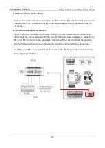
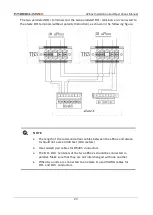
When one unit is connected to an aGate X, the 485A and 485B terminals on the aPbox
TB3 module are connected to the RS485 A1 and B1 terminals on the aGate X, respectively,
DO+ and DO- terminals to the aGate DO terminals (without distinguishing the polarity).
Use the following diagram as a reference when making communications connections.
1
)
When one aPbox is installed on the load side of the FHP system, the communications
wiring figure is as follows.

