2
Installation
Overview
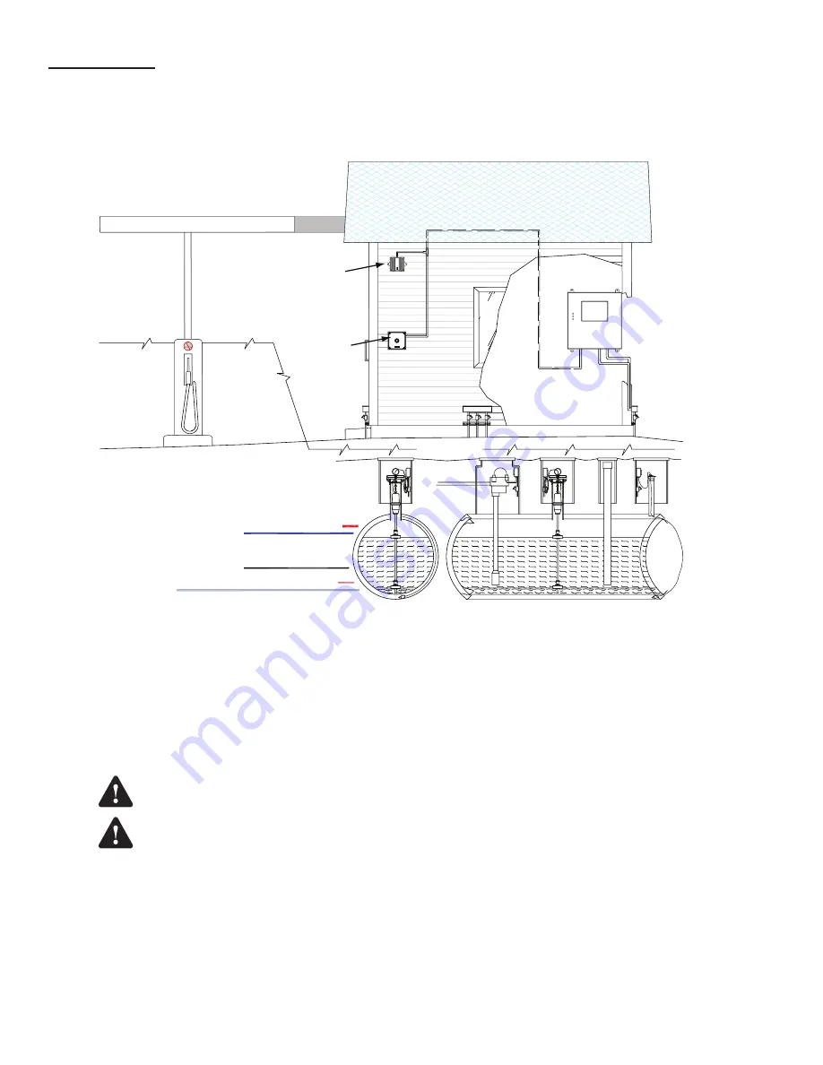
The mounting location of TS-RA1, TS-RA2, TS-RK units should be based on: cable run length, ease of conduit routing,
alarm light visibility, alarm horn audible range limitations, and the distance away from hazardous areas. In addition, the
following limitations and requirements must be met.
TANK OVERFILL ALARM
LOW Limit
(Reorder) setpoint
HIGH Limit
(Tank full) setpoint
(high)WATER
Limit setpoint
HI HI Limit
(Tank Overfill) setpoint
LO LO Limit setpoint
HAZARDOUS
AREA
TS-RK
Alarm Acknowledge
Unit
NON-HAZARDOUS
AREA
TS-RA1, or TS-RA2
Tank Overfill Alarm
(TS-RA2 shown)
FMS
Console
NON-HAZARDOUS
AREA
Tank Filling Site
HAZARDOUS
AREA
MODEL TS-RK
SACO, MAINE 04072
INTELLIGENT CONTROLS INC.
ACKNOWLEDGE
74 INDUSTRIAL PARK ROAD
SACO, MAINE 04072
INTELLIGEN
T
CONTROLS
74 INDUSTRIAL
PA
RK RD
.
TA
NK OVERFILL
ALAR
M
MODE
L
TS-RA2
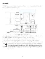
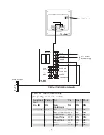
Figure 1: TS-RA and TS-RK Installation Overview
• The location of the Tank Overfill Alarm and Alarm Acknowledge unit enclosures must be less than 1000 feet away from
the 120 VAC electrical power (source) panel.
• The TS-RA1, or TS-RA2 Tank Overfill Alarm unit should be mounted near the fuel tank filling area.
• The alarm light must be visible and the alarm horn must be audible at the fuel tank filling area.
• These units should be mounted in a protected location that minimizes exposure to direct sunlight, snow and rain.
• The TS-RK Tank Overfill Alarm Acknowledge unit should be accessible to the tank filling attendant. Access to the TS-RK
from the filling area must be clear with no obstructions.
DO NOT install the Tank Overfill Alarm, or Alarm Acknowledge units in a volatile, combustible, or
explosive atmosphere. Failure to do so may create an explosion hazard.
Run wiring from the Tank Sentinel console to the TS-RA1 / TS-RA2 Tank Overfill Alarm, and TS-RK
Alarm Acknowledge units in separate conduit apart from any other wiring. All conduits must enter
through supplied non-intrinsically safe enclosure knockouts only. Failure to do so may create an
explosion hazard.
Warning
Warning
Содержание TS-RA1
Страница 8: ...FFS 2018 000 1027 r7...

