1
Important Safety Messages
FFS equipment is designed to be installed in association with volatile hydrocarbon liquids such as gasoline and diesel fuel. Installing or
working on this equipment means working in an environment in which these highly flammable liquids may be present. Working in such
a hazardous environment presents a risk of severe injury or death if these instructions and standard industry practices are not followed.
Read and follow all instructions thoroughly before installing or working on this, or any other related, equipment.As you read this guide,
please be aware of the following symbols and their meanings:
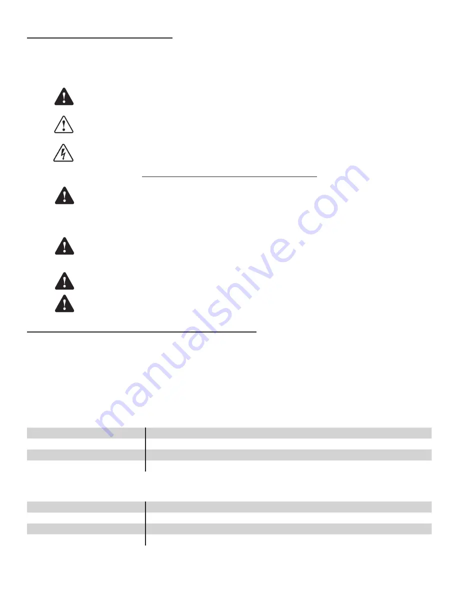
This symbol identifies a warning. A warning sign will appear in the text of this document when a potentially hazardous
situation may arise if the instructions that follow are not adhered to closely. A potentially hazardous situation may
involve the possibility of severe bodily harm or even death.
This is a caution symbol. A caution sign will appear in the text of this document when a potentially hazardous
environmental situation may arise if the instructions that follow are not adhered to closely. A potentially hazardous
environmental situation may involve the leakage of fuel from equipment that could severely harm the environment.
This symbol identifies an electrical danger. An electrical danger sign will appear in the text of this document when a
potentially hazardous situation involving large amounts of electricity may arise if the instructions that follow are not
adhered to closely. A potentially hazardous situation may involve the possibility of electrocution, severe bodily harm, or
even death.
Follow all applicable codes governing the installation and servicing of this product and the entire system.
Always lock out and tag electrical circuit breakers while installing or servicing this equipment and any
related equipment. A potentially lethal electrical shock hazard and the possibility of an explosion or fire from
a spark can result if the electrical circuit breakers are accidentally turned on during installation or servicing.
Please refer to the Installation and Owner’s Manual for this equipment, and the appropriate documentation
for any other related equipment, for complete installation and safety information.
Follow all federal, state and local laws governing the installation of this product and its associated systems.
When no other regulations apply, follow NFPA codes 30, 30A and 70 from the National Fire Protection
Association. Failure to follow these codes could result in severe injury, death, serious property damage and/
or environmental contamination.
When the Fuel Management System system is used to monitor tanks containing gasoline or other flammable
substances, you may create an explosion hazard if you do not follow the requirements in this manual
carefully.
All wiring from probes or sensors to the console must be run in conduit separate from all other wiring.
Failure to do so will create an explosion hazard.
Product Overview and Theory of Operation
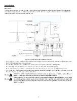
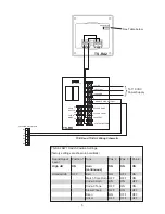
The TS-RA1, and TS-RA2 are remote audible and visual alarm units that are used with Fuel Management System consoles. The TS-
RA1, TS-RA2, and the TS-RK
Tank Overfill Alarm and Alarm Acknowledge
units are mounted near the tank filling site. If the tank
product level reaches the FMS overfill alarm setpoint, then the Tank Overfill Alarm will become active. An active Tank Overfill Alarm
alerts the tank filling attendant to immediately stop the filling operation before a spill occurs. The TS-RK is an optional remote alarm
acknowledge unit. This unit gives the tank filling attendant the means to silence a Tank Overfill Alarm at the filling site. The TS-RK is
required when a TS-RA1 or TS-RA2 is connected to a T5 series Fuel Management System console or a Colibri Automatic Tank Monitor.
When in an alarm condition, depressing the acknowledge button on the TS-RK will silence the Tank Overfill Alarm at the tank filling site.
Alarm Specifications
The TS-RA1 is a standard intensity, remote alarm device that has a useful signal range up to 50 feet.
Ratings
Input Power
115 VAC (96 to 132vac), 60Hz @ 0.125 amps Maximum
Operating Temperature Range
–31 to 150 °F
Humidity Range
Up to 95% humidity
Signal outputs
Visual (low intensity incandescent lamp) & audio tone (85 dB @ 10 feet)
The
TS-RA2
is alarm device that has a strobe-light, and eight user-selectable output tones with two user-selectable sound intensities.
In the high-intensity mode, the TS -RA2 has a useful signal range up to 200 feet.
Ratings
Input Power
115 VAC (96 to 132vac), 60Hz @ 0.125 amps Maximum
Operating Temperature Range
–31 to 150 °F
Humidity Range
Up to 95% humidity
Signal outputs
Visual strobe (15 Candela), and audio tone (99 dB to 75 dB @ 10 feet).
When properly installed, wired, and programmed, this alarm system will help prevent dangerous fuel spills, environmental
contamination, and cleanup costs.
Danger
Warning
Warning
Warning
Warning
Warning
Caution
Содержание TS-RA1
Страница 8: ...FFS 2018 000 1027 r7...

