background image


IN 3H06/08/12/15 

- 17 - 

© Future Products Group 

SERVICING 


Control Gear 

HEATED CABINETS 

 - 

SERVICING 


Location 

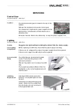
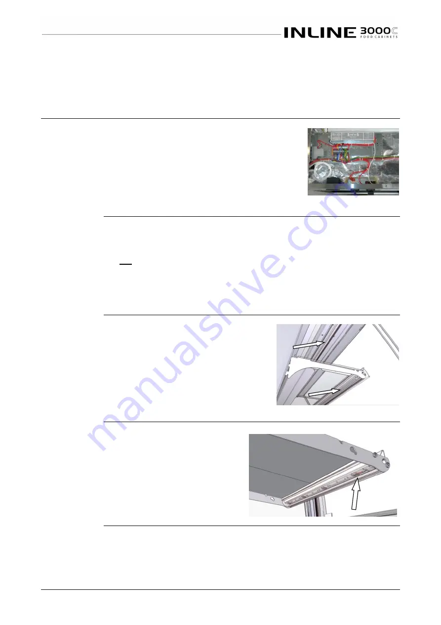
The electrical control gear is located in the top of the 
cabinet. 

Remove the top plate to access the control gear. 

The chassis has a light switch, power supplies for the 
lights and fan, a thermostat, a thermometer and a 
protective fuse.  

Extraction fans are fitted in the cabinet top, to keep the power supplies cool. 


Lighting 

HEATED CABINETS 

 - 

SERVICING 


Caution 

Do not service lights without isolating the cabinet from the mains supply. 

Test Lighting 
Components 

Before replacing an LED strip, check that its power supply is working. 

If there is no dc voltage at the output, the power supply should be replaced. 

If there is a dc output, the LED strip must be replaced.  


Access to LED 
Strips 

The LED strips are protected with plastic 
covers. These clip into grooves in the 
aluminium extrusion. 

Remove the plastic cover to access the LED 
strip. 

The top light assembly is different from the 
shelf lights, so the correct replacement unit 
must be used. 


LED Strip 
Replacement 

Individual LED modules cannot be 
replaced.  A complete light unit must 
be used. 

Connection is made with a plug and 
socket.  Disconnect the supply lead 
from the faulty unit, and reconnect it 
to the replacement unit. 


Содержание IN 3H06

Страница 1: ...Heated Cabinets Curved Format...

Страница 2: ...uture Products Group Limited All rights reserved No part of this publication may be reproduced stored in a retrieval system or transmitted in any form or by any means electronic mechanical photocopyin...

Страница 3: ...ets 8 Lighting 8 Controls 8 Light Switch 8 Heating 8 Thermometer 8 Preparation 9 Shelf Location and Ticketing 9 Shelf Adjustment 9 Power Supply 9 Set the Temperature 9 Fumes and Odours 9 Load Cabinet...

Страница 4: ...n 14 Shelf Trays 14 Grounding 15 Power Supply 15 Isolation 15 Location 15 Ventilation 15 Access 15 Fumes and Odours 15 Livery 16 Custom Inserts 16 SERVICING 17 Control Gear 17 Location 17 Lighting 17...

Страница 5: ...21 Improvements 21 Ongoing Development 21 ELECTRICAL CIRCUIT DIAGRAMS 22 Model IN 3H06 22 Model IN 3H08 22 Model IN 3H12 23 Model IN 3H15 23 SPARE PARTS 24 Cabinet Serial Number 24 Handed Parts 25 MEC...

Страница 6: ...w its recommendations The time taken will be well spent These instructions both general and technical tell you how to install operate and look after your inline food service cabinet so that you can re...

Страница 7: ...e or malfunction resulting from the use of non FPG supplied spare parts Specific Exclusions The following are specifically excluded from warranty Breakage of glass or plastic components or the replace...

Страница 8: ...the cabinet Lighting All cabinets are fitted with high efficiency LED lighting strips in the ceiling of the cabinet as standard Additional LED strips below each shelf are available as an optional ext...

Страница 9: ...y and then pull the brackets forward to disengage them from the slots in the support posts Insert the brackets into their new position and push bracket down firmly The brackets may be positioned to gi...

Страница 10: ...et base Close all Doors It is important to keep all cabinet doors closed If doors are not fully closed an even temperature will not be maintained within the cabinet Turn on Lights When ready for servi...

Страница 11: ...ecked and replace fuse 5A Slow Blow Cabinet does not reach temperature One or more doors is open Close doors and re test temperature after thirty minutes Thermostat setting disturbed Re set thermostat...

Страница 12: ...an surfaces with abrasive pads or cleaners e g Scotchbrite pads or Jif as paint stainless steel and aluminium surfaces will be damaged Glass All glass should be cleaned using a good quality glass clea...

Страница 13: ...etc should be cleaned with hot soapy water Do not use abrasive pads or cleaners e g Scotchbrite pads or Jif as these may damage surfaces Warning Dishwasher detergents will damage any anodised aluminiu...

Страница 14: ...ation Ensure the cabinet location and any bench cut outs are made to the precise measurements shown in the Mechanical Drawings Position the cabinet in its allocated working position Use a spirit level...

Страница 15: ...cabinet Isolation If the cabinet is not connected by a plug and socket but is hard wired to the mains supply a means of isolation must be provided If a plug and socket are used they should still be a...

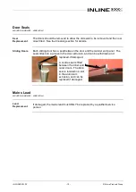
Страница 16: ...aptive by the cabinet ends and has to be bowed for removal and insertion Insert the upper edge into the narrow groove closest to the curved surface bow the strip to insert the end into the lower groov...

Страница 17: ...est Lighting Components Before replacing an LED strip check that its power supply is working If there is no dc voltage at the output the power supply should be replaced If there is a dc output the LED...

Страница 18: ...withdraw it to reveal the connections Disconnect the old element connect the replacement taking care to replace and refit any insulation material Position the new element against the bulkhead clip it...

Страница 19: ...ding door has a seal between the door and the cabinet end panel The seal slides into a groove in the door extrusion and can be withdrawn and replaced if damaged A centre seal is fitted between the inn...

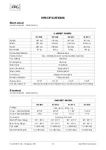
Страница 20: ...s ends Double glazed Front Doors Sliding or Fixed options Number of Shelves Three plus base Display Area 0 7 m2 0 9 m2 1 4 m2 1 8 m2 Climatic Class IP Cabinets are tested under Climate Class 2 conditi...

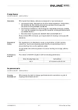
Страница 21: ...NZS 3820 and AS NZS 4417 Please contact FPG to discuss your requirements for meeting country specific standards Operational Safety This appliance is not intended for use by young children or infirm p...

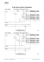
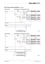
Страница 22: ...art No 26118 Rev H September 2018 22 Inline 3000 Series Cabinets ELECTRICAL CIRCUIT DIAGRAMS Model IN 3H06 Inline 3000 Series 600mm Heated Cabinet Model IN 3H08 Inline 3000 Series 800mm Heated Cabinet...

Страница 23: ...IN 3H06 08 12 15 23 Future Products Group ELECTRICAL WIRING DIAGRAMS Continued Model IN 3H12 Inline 3000 Series 1200mm Heated Cabinet Model IN 3H15 Inline 3000 Series 1500mm Heated Cabinet...

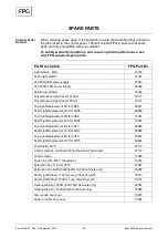
Страница 24: ...0mm 18114 Top Light Replacement Kit for 3H06 69871 Shelf Light Replacement Kit for 3H06 69839 Top Light Replacement Kit for 3H08 71647 Shelf Light Replacement Kit for 3H08 70397 Top Light Replacement...

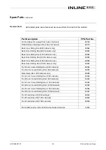
Страница 25: ...binets only 62666 Back Outer Sliding Door 1500 cabinets only 62667 Front Inner Curved Sliding Door 600 cabinets 66934 Front Outer Curved Sliding Door 600 cabinets 66935 Rear Swing Door 600 cabinets on...

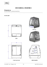
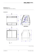
Страница 26: ...Part No 26118 Rev H September 2018 26 Inline 3000 Series Cabinets MECHANICAL DRAWINGS Dimensions HEATED CABINETS MECHANICAL DRAWINGS IN 3H06 A002...

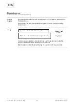
Страница 27: ...IN 3H06 08 12 15 27 Future Products Group Dimensions cont HEATED CABINETS MECHANICAL DRAWINGS IN 3H08 12 15 Continued on next page...

Страница 28: ...BINETS MECHANICAL DRAWINGS Cabinet Variants The drawings show the common overall dimensions for 800mm 1200mm and 1500mm cabinets The cabinets can have a single fixed front glass in place of the twin s...

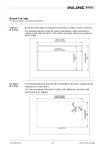
Страница 29: ...ollowing diagram shows the aperture dimensions which will allow the cabinet well to enter the bench The cabinet deck trays will then be just above bench height On Bench Mounting The following diagram...

Страница 30: ...Part No 26118 Rev H September 2018 30 Inline 3000 Series Cabinets...

Страница 31: ...IN 3H06 08 12 15 31 Future Products Group...

Страница 32: ...to change specifications and design without notice AUSTRALIA E ausales fpgworld com T 1800 813 745 CHINA ASIA E asales fpgworld com T 86 21 3351 3390 EUROPE E eusales fpgworld com T 31 6 5253 4769 IND...

Отзывы: