background image

This manual is the intellectual property of Foxconn, Inc. Although the

information in  this manual may be  changed or modified at  any time,

Foxconn does not obligate itself to inform the user of these changes.

Statement:

All trademarks are the property of their respective owners.

More information:

If you want more information about our products, please visit Foxconn

s

website: 

 http://www.foxconnchannel.com

This product and its accessories are produced after 13th Aug., 2005 and

comply with the W EEE2002/96EC directive.

Version:

Trademark:

User

s Manual V1.0 for Q9657MC/G9657MC motherboard.

P/N:91-181965MC0E-00-G

Symbol description:

Note:

 refers to important information that can help you to use motherboard

better.

Attention:

 indicates that it may damage hardware or cause data loss,

and tells you how to avoid such problems.

Warning: 

means that a potential risk of property damage or physical

injury exists.

PDF 

文件使用

 "pdfFactory" 

试用版本创建


Æ


Æ


www.fineprint.com.cn

Содержание G9657MC

Страница 1: ...e visit Foxconn s website http www foxconnchannel com This product and its accessories are produced after 13th Aug 2005 and comply with the WEEE2002 96EC directive Version Trademark User s Manual V1 0 for Q9657MC G9657MC motherboard P N 91 181965MC0E 00 G Symbol description Note refers to important information that can help you to use motherboard better Attention indicates that it may damage hardw...

Страница 2: ...e characteristics of information technology equipment þ EN 61000 3 2 2000 Electromagnetic compatibility EMC Part 3 Limits Section 2 Limits for harmonic current emissions equipment input current 16A per phase þ EN 61000 3 3 A1 2001 Electromagnetic compatibility EMC Part 3 Limits Section 2 Limits of voltage fluctuations and flicker in low voltage supply systems for equipment with rated current 16A þ...

Страница 3: ...nufacturer HON HAI PRECISION INDUSTRY COMPANY LTD Address 66 CHUNG SHAN RD TU CHENG INDUSTRIAL DISTRICT TAIPEI HSIEN TAIWAN R O C SupplementaryInformation This device complies with Part 15 of the FCC Rules Operation is subject to the follow ing two conditions 1 this device may not cause harmful interference and 2 this device must accept any interference received including interference that may cau...

Страница 4: ...S Setup 19 Main menu 19 Product Information 21 Standard CMOS Features 22 Advanced BIOS Features 25 Advanced Chipset Features 27 Integrated Peripherals 28 Power Management Setup 32 PnP PCI Configurations 35 PC Health Status 36 Frequency Control 38 Load Defaults Setting 39 Set Supervisor User Password 39 Save Exit Setup 40 Exit Without Saving 40 Table of Contents Chapter 1 1 Chapter 2 2 Chapter 3 3 ...

Страница 5: ...Driver CD Introduction Utility CD content 42 Install drivers 42 Table of Contents 4 4 Chapter ...

Страница 6: ...ure to switch off the DC power supply may result in serious damage to your system or memory module Attention We cannot guarantee that your system will operate normally while over clocked Normal operation depends on the over clock capacity of your device Attention Attention Since BIOS programs are upgraded from time to time the BIOS description in this manual is just for reference We do not guarant...

Страница 7: ...6 with 6 Channel audio Default is omitted 8 with 8 Channel audio E with 1394 S with SATA 2 with DDR2 R with RAID H complay with RoHS directives You can find PPID label on the motherboard It indicates the functions that the motherboard has For example The letters on the black mark of the PPID label mean the motherboard supports 6 Channel Audio 6 default 1394 port E onboard 10 100M LAN L default SAT...

Страница 8: ...s superior performance reliability and quality at a reasonable price This motherboard adopts the advanced Intel Q G965 ICH8DO ICH8DH chipset providing users a computer platform with a high integration compatibil ity performance price ratio This chapter includes the following information v Main Features v Layout v Rear I O Ports 1 1 ...

Страница 9: ...stem Memory Four 240 pin DIMM slots Supports Dual Channel DDR2 533 667 800 Supports up to 8GB DDR2 memory USB 2 0 Ports Supports hot plug Ten USB 2 0 ports four rear panel ports three onboard USB headers providing six extra ports Supports wake up from S1 and S3 mode Supports USB 2 0 protocol up to 480Mbps transmission rate Onboard Serial ATA II 300MBps data transfer rate Supports hot plug and NCQ ...

Страница 10: ...Definition Audio Onboard Graphics Supports integrated VGA display function PCI Express x16 Support Supports 4 GB sec 8 GB sec concurrent bandwidth Low power consumption and power management features Green Function Supports ACPI Advanced Configuration and Power Interface Supports S0 normal S1 power on suspend S3 suspend to RAM S4 Suspend to disk depends on OS and S5 soft off Expansion Slots Two PCI...

Страница 11: ... Chipset 25 LGA 775 CPU Socket 1 4 pin ATX_12V Power Connector PWR2 2 PCI Express x16 Slot 3 PCI Express x1 Slot 4 1394 Connector optional 5 PCI Slots 6 AUX_IN Connector 7 Front Audio Connector 8 SPDIF_OUT Connector optional 9 Front USB Connectors 10 BIOS SEL1 Jumper 11 SATA II Connectors 12 Front Panel Connector 13 TPM Connector optional Note The above motherboard layout is provided for reference...

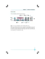
Страница 12: ...GA Connector USB 2 0 Ports Lan Port K 1394 Connector optional Line in Line out Microphone Rear LEF CEN Side Jacks When using 8 channel sound source connect the front speaker to the green audio output connect the rear sound speaker to the black audio output con nect the center speaker subwoofer to the orange audio output connect the side sound speaker to the grey audio output 6 ...

Страница 13: ...d pin headers and the mounting of jumpers Cau tion should be exercised during the installation of these modules Please refer to the motherboard layout prior to any installation and read the contents in this chapter carefully This chapter includes the following information v CPU v Memory v Power supply v Other Connectors v Expansion Slots v Jumpers Chapter2 2 ...

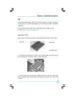
Страница 14: ...e http www foxconnchannel com Installation of CPU Below is the CPU socket illustration Follow these procedures to install a CPU Load lever Load plate Protective cover 1 Use thumb and forefinger to hold the hook of the load lever and pull the lever down and away from socket to unlock it Lift the load lever 2 Push down the rear tab with your forefinger to bring the front end of the load plate up sli...

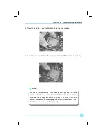
Страница 15: ...ovides the orientation directed function Lower the CPU straight down without tilting or sliding the CPU in the socket 4 After installing the CPU remove the protective cover from load plate The protective cover is used to protect the contacts of the socket Do not discard the protective cover Always replace the socket cover if the CPU is removed from the socket Alignment Key SocketCutouts Pin 1 posi...

Страница 16: ...U cooling fan and make sure that the cooling fan works normally at all times in order to prevent overheating and damaging to the CPU Please refer to your CPU fan user guide to install it properly 5 Close the load plate and slightly push down the tongue side 6 Lower the lever and lock it to the load plate then the CPU is locked completely ...

Страница 17: ... the center of the DIMM slot and the memory module can be fixed in one direction only Unlock a DIMM slot by pressing the module clips outward 2 Align the memory module to the DIMM slot and insert the module vertically into the DIMM slot 3 The plastic clips at both sides of the DIMM slot will lock automatically 128 Pins 112 Pins For the detailed memory support list on this motherboard please visit ...

Страница 18: ...ke sure that the power supply cable and pins are properly aligned with the connector on the motherboard Firmly plug the power supply cable into the connector and make sure it is secure 4 pin ATX_12 V Power Connector PWR2 The 4 pin ATX 12V power supply connects to PWR2 and provides power to the CPU 4 pinATX_12 V Power Connector 12V GND 12V 3 1 4 2 GND 13 3 3V 5V GND 3 3V GND PWROK 3 3V 24 5V GND 3 ...

Страница 19: ...activity status of hard disks Reset Switch RESET Attach the connector to the Reset switch on the front panel of the case the system will restart when the switch is pressed Power LED Connector PWRLED Attach the connector to the power LED on the front panel of the case The Power LED indicates the system s status When the system is in S0 status the LED is on When the system is in S1 status the LED is...

Страница 20: ...R Mode from the Integrated Peripher als section of the CMOS Setup IR 1 5V GND IRRX IRTX Empty 1394 Connector F_1394 optional The 1394 expansion cable can be con nected to either the front provided that the front panel of your chassis is eq uip p ed w ith t h e ap pr o p r iat e interface or real panel of the chassis 1 2 GND 12V TPB GND TPA 12V TPB GND TPA Empty F_1394 9 10 SPDIF_OUT 1 SPDIF_OUT 5V...

Страница 21: ...connects to the chassis security switch on the case The system can detect the chassis intrusion through the status of this connector If the connector has been closed once the system will send a message INTR 1 INTRUDERJ 2 GND Audio Connectors AUX_IN AUX_IN is Sony standard CD audio connectors it can be connected to a CD ROM drive through a CD audio cable AUX_IN 1 CD_R GND CD_L COM Connector COM2 Th...

Страница 22: ..._SYS L_AD0 NC GND NC LPCPDJ L_AD2 L_AD1 GND NC SERIRQ NC GND TPM Connector TPM optional The TPM Trusted Platform Module provides the ability to the PC to run applications more secure and to make transactions and communication more trustworthy To utilize this function you should purchase addtional device and install it Fan Connectors CPU_FAN1 SYS_FAN The fan speed can be detected and viewed in PC H...

Страница 23: ...ndwidth between the x16 x4 and x1 slot is notable to be sure with the x16 slot pushing 4GB sec 8GB sec concurrent of bandwidth the PCI Express x4slot offering 500MB sec and the PCI Express x1 slot offering 250MB sec Installing an expansion card 1 Before installing the expansion card read carefully the documentation that came with it and make the necessary hardware settings for the card 2 Make sure...

Страница 24: ...er to this when adjusting jumper settings Jumper Diagram Definition Description 1 2 Set pin1 and pin2 closed 2 3 Set pin2 and pin3 closed Closed Set the pin closed Open Set the pin opened 1 1 1 1 1 1 Clear CMOS Jumper CLR_CMOS The motherboard uses the CMOS RAM to store all the set parameters The CMOS can be cleared by removing the CMOS jumper How to clear CMOS 1 Turn off the AC power supply and co...

Страница 25: ...n during the system POST process 2 You want to change the default CMOS settings This chapter includes the following information v Enter BIOS Setup v Main Menu v Product Information v Standard CMOS Features v Advanced BIOS Features v Advanced Chipset Features v Integrated Peripherals v Power Management Setup v PnP PCI Configurations v PC Health Status v Frequency Control v Load Defaults Setting v S...

Страница 26: ...OST Screen DEL to enter SETUP Main Menu The main menu allows you to select from the list of setup functions and two exit choices Use the arrow keys to select among the items and press Enter to accept or go to the sub menu The items in the main menu are explained as below Product Information The product information can be seen through this menu Standard CMOS Features The basic system configuration ...

Страница 27: ...p through this menu PnP PCI Configurations The system s PnP PCI settings and parameters can be modified through this menu PC Health Status This will display the current status of your PC Frequency Control This menu is used to set the frequency Load Defaults Setting The default BIOS settings can be loaded through this menu Set Supervisor Password The supervisor password can be set up through this m...

Страница 28: ...n see the information of the product which includes the system name motherboard product name system S N motherboard S N system manufacture name motherboard manufacture name system BIOS version SMBIOS version system BIOS ID BIOS release time and so on and makes users to know the system information clearly ...

Страница 29: ...me This option allows you to set up the desired time usually as the current time with hour minute second format IDE Channel 0 1 2 3 Master 0 1Slave These categories identify the HDD types of 1 IDE channel installed in the com puter system There are three choices provided for the Enhanced IDE BIOS None Auto and Manual None means no HDD is installed or set Auto means the system can auto detect the h...

Страница 30: ...l be prompted No Errors The system boot will not stop for any errors that may be detected All But Keyboard The system boot will not stop for a keyboard error but it will stop for all other errors All But Diskette The system boot will not stop for a diskette error but it will stop for all other errors All But Disk Key The system boot will not stop for a keyboard or disk error but it will stop for a...

Страница 31: ...ned by POST Power On Self Test of the BIOS Base Memory The BIOS POST will determine the amount of base or conventional memory installed in the system Extended Memory The BIOS determines how much extended memory is present during the POST Total Memory Total memory of the system ...

Страница 32: ...ct the entire hard disk vQuick Power On Self Test This option is used to set the Quick Power On Self Test vFirst Second Third Boot Device This option allows you to set the boot device s sequence vBoot Other Device With this function set to enable the system will boot from some other de vices if the first second third boot devices failed The setting values are Dis abled and Enabled vBoot Up Floppy ...

Страница 33: ...sion Control For OS This option is used to set up the version of MPS Table used in OS vSilent Boot The item is used to enable or disable the silent boot vConfiguration Table The item is used to show summary screen vASF support The item is used to enable or disable the ASF support vDMI Event Log Enable the item the system will store POST error messages to the DMI event log vClear All DMI Event Log ...

Страница 34: ...ontrol This item is used to enable or disable PEG and onboard VGA vOn chip Frame Buffer Size This item is used to set the VGA frame buffer size Note This function does not work when the external display card is used vDVMT Mode The item is used to set the DVMT mode vDVMT FIXED Memory Size The item is used to set the DVMT FIXED memory size Advanced Chipset Features Menu ...

Страница 35: ...ption 28 Integrated Peripherals vOnChip IDE Device Press enter to set onchip IDE device vOnboard Device Press enter to set onboard device vSuperIO Device Press enter to set onboard SuperIO device Integrated Peripherals Menu ...

Страница 36: ...vices If you install a device that supports UltraDMA change the appropriate item on this list to Auto The available setting values are Disabled and Auto vOn Chip Secondary PCI IDE Use this item to enable or disable the Secondary PCI IDE channel that is in tegrated on the motherboard vIDE Secondary Master Slave PIO These two items allow you assign which kind of PIO Programmed Input Output is used b...

Страница 37: ...e USB keyboard controller is enabled in a legacy operating system such as DOS vUSB Mouse Support This option is used to set whether the USB mouse controller is enabled in a legacy operating system such as DOS vOnboard Lan Controller This option is used to set whether the onboard LAN controller is enabled vAzalia Audio This option is used to set whether onboard Azalia Audio is enabled v Onboard LAN...

Страница 38: ... IRQ for the onboard serial port Note Do not try to set the same values for serial ports 1 and 2 vOnboard Parallel Port This option allows you to determine onboard parallel port controller I O ad dress and interrupt request IRQ vParallel Port Mode Select an address and corresponding interrupt for the onboard parallel port vECP Mode Use DMA When the Parallel Port Mode is set to ECP or ECP EPP this ...

Страница 39: ...ing mode of the ACPI function When you select S1 POS mode the power will not shut off and the supply status will remain as it is in S1 mode the computer can be resumed at any time When you select S3 STR mode the power will be cut off after a delay period The status of the computer before it enters STR will be saved in memory and the computer can quickly return to previous status when the STR funct...

Страница 40: ...evant hardware and software vUSB KB Wake Up From S3 This item is used to set the system to wake up by USB equipment when it is in S3 Suspend to RAM mode vResume by Alarm This item is used to set the timing of the start up function In order to use this function the start up password function must be canceled Also the PC power source must not be turned off The setting values are Disabled and Enabled...

Страница 41: ...pter 3 BIOS Description 34 PCI Express PM Function Menu vPCI Express PME Function This item is used to set whether the system can be waked up by PCI Express PME The setting values are Enabled and Disabled ...

Страница 42: ...o ISA slot this option doesn t apply v Resources Controlled By This option is used to set whether the system is permitted to automatically distribute IRQ DMA and I O addresses when each time that the machine is turned on The setting values are Disabled and Enabled vIRQ Resources Press the Enter key then manually set IRQ resources vPCI VGA Palette Snoop If you use a non standard VGA card use this o...

Страница 43: ...y the system vCPU SYS CPU Relative Temperature The CPU system CPU relative temperature will be automatically detected by the system vCPU SYS FAN Speed The CPU and system fan speed will be automatically detected by the system vCPU Temp Offset The item is used to change the CPU temperature When you change the CPU temperature Offset value the CPU temperature can be changed accordingly PC Health Statu...

Страница 44: ...Chapter 3 BIOS Description 37 vFan1 2 3 Speed Monitor The items are used to set whether the Fan1 2 3 speed monitors are enabled Advanced Fan Speed Control Menu ...

Страница 45: ...tect PCI Clk This option is used to set whether the clock of an unused PCI slot will be disabled to reduce electromagnetic interference The setting values are Disabled and Enabled vSpread Spectrum If you enable spread spectrum it can significantly reduce the EMI Electro Magnetic Interference generated by the system The setting values are Disabled and Enabled Frequency Control Menu ...

Страница 46: ...igher than those of a regular User password The Supervisor password can be used to start the system or modify the CMOS settings The User password can also start the system While the User password can be used to view the current CMOS settings these settings cannot be modified using the User password When you select the Set Supervisor User Password option the following message will appear in the cen...

Страница 47: ...r of the screen Quit Without Saving Y N N Press Y to exit CMOS without saving your modifications press N or ESC to return to the main menu Under the menu Advanced BIOS Features if you select System from the Security Option you will be prompted to enter a password once the system is started or whenever you want to enter the CMOS setting program If the incorrect password is entered you will not be p...

Страница 48: ... The utility CD that came with the motherboard contains use ful software and several utility drivers that enhance the motherboard features This chapter includes the following information v Utility CD content v Install drivers 4 4 Chapter ...

Страница 49: ...automatically displays the main menu screen Install Driver Using this choice you can install all the drivers for your motherboard You should install the drivers in order and you need to restart your computer after the drivers all installed A Intel Chipset Driver B Realtek HDA Audio Driver C Intel LAN Driver D Intel VGA Driver E Intel ME Interface Driver F Intel AMT ME Driver ...

Отзывы: