1. GENERAL
Pressure/vacuum switches are electro mechanical equipments which send an electric or pneumatic signal as a fixed value of pressure (or negative pressure) is reached.
Depending of the using, there are two different types:
1.1 Diaphragm pressure/vacuum switch (
M
):
mechanical type, very sensible, for
very low pressures.
1.2 Piston pressure switch (
P
):
mechanical type, less sensitive but fit for higher
pressures.
WARNING!
• A pressure/vacuum switch
isn’t
a safety device!
• Fixing, wiring and settings must be performed by qualified staff, and only after a careful reading of this User’s Guide.
2. TECHNICAL
DATA
2.1
This User’s Guide and Maintenance Reference must be considered an integrating part of the shipment. Always check that the goods received are integral and corresponding
to the order. Compare the inscription printed on the label of the equipment, on the order and on the delivery note, issued by
FOX s.r.l.
; in case of discordance, don’t install the
instrument on the system but contact immediately
FOX Srl.
2.2
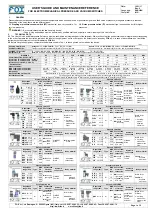
Before fixing the equipment, compare technical data shown in Tab. 1 to those printed on the label on the device.
Tab.1
Shaping, material and
treatment standards:
Hexagons:
Ch. 24 (
K4-F4-WF4
), Ch. 27 (
F3
), Ch. 32 (
K9
).
Trivalent zinking steel. Available in (
X
) AISI 316L and (
L
) brass.
Square:
30x30 mm (
K6-K7-KR6-F5
), 40x40 mm (
F3S-K5-K51-W3
).
Anodized aluminium. Available in (
X
) AISI 316L and (
L
) nickel plated brass.
min/MAX (°C) working
temperature, TS:
TS -20÷+80 (
K4 - F3 - F3S - K6 - KR6 - K7 - K9 - F5 - K5 - K51 - W3 - WF4
)
TS -25÷+85 (
F4
)
Note:
Min. and Max. working temperature are the project installation, or the pressurised circuit temperature.
WORKING
K4
F4
F3
F3S
K6-KR6
K7
K9
F5
K5
K51
W3
WF4
Commutation freq. (cycles/min
1
):
90 90 90 90 90 120
120
120
120
120 90 60
Hysteresys (% setting at 20°C – diaph.):
Hysteresys (% setting at 20°C - piston):
~10
~20
~10
~15
~10
~15
~7
-
~10
~15
~15
~15
-
~15
-
~15
-
~15
~10
-
~15
-
~20
-
Intervention precision (% at 20°C):
±5 ±4 ±4 ±3 ±4 ±3 ±2 ±3 ±2 ±2 ±7 ±15
*Operating point:
3
3
4
4
4
4
4
4
5
5
5
5
6
6
5
5
3
3
(P 7
7
) 3
3
(P 7
7
) 4
4
4
4
Signal condition:
D
means setting for lowering pressure;
U
means setting for rising pressure
MAX Loading Am at Volt-(AC):
MAX Loading Am at Volt-(DC):
0.5-250
0.25-125
0.5-250
0.25-125
0.5-250
0.25-125
0.5-250
0.25-125
0.5-250
0.25-125
5.0-250
0.25-250
5.0-250
0.25-250
5.0-250
0.1-250
5.0-250
0.25-250
5.0-250
0.25-250
3.0-125
0.25-125
3.0-125
0.25-125
Weight (kg):
0,06 0,05 0,08 0,10 0,20 0,20 0,40 0,15 0,35 0,35 0,10 0,055
Mechanical and electrical life:
Mechanical life is, for all, 10
6
cycles at 70 bar (1000 psi), at 20 °C
Electrical life is, for all, inversely proportional to the contacts loading.
Installation position:
For all: position is non relevant, as soon as the technical room for connection fixing/removing is provided
*Note on trigger:
3
3
External screw;
4
4
Internal screw;
5
5
Internal screw, protected by a safety cap;
6
6
External gear;
7
7
Knob
Pressure switch - K4
Regulation
range (bar)
Type
MAX
PS
(bar)
Contact and
electrical
connection
Hydraulic
connection
Body material
R
0.2÷2.5
M 25
A
=NO
C
=NC
F
=6.3mm
fast-on end.
O
=screwed
conn.
0
=1/8”BSP
1
=1/4”BSP
2
=1/8”BSPT
3
=M10x1
4
=1/8”NPT
5
=1/4”NPT
6
=1/4”BSPT
X
=AISI 316L
L
=Brass
B
=Nickel plated
brass
-
If missing,
means zinc-
plated carbon
steel
S
1÷12
SM
1÷12
M
150
SP
1÷12
P
300
T
5÷50
P
300
TM
5÷50
M
150
V
10÷100
P
300
VM
1÷12
M 150
Z
20÷200
P
300
Y
50÷400
P
600
Pressure switch F4
Regulation
range (bar)
Type
MAX
PS
(bar)
Contact and
electrical
connection
Hydraulic
connection
Body material
R
0,2÷2,5
M
25
P3
=6,3x0,8
Fast-on
M2
=16x16
connector
M3
=30x30
connector
0
=1/8”BSP
1
=1/4”BSP
2
=1/8”BSPT
3
=M10x1
4
=1/8”NPT
5
=1/4”NPT
6
=1/4”BSPT
X
=AISI 316L
L
=Brass
B
=Nickel plated
brass
-
If missing,
means zinc-
plated carbon
steel
S
1÷12
SM
1÷12
150
SP
1÷12
P
300
T
5÷50
P
300
TM
5÷50
M
150
V
10÷100
P
300
VM
1÷12
M
150
Z
20÷200
P
300
Y
50÷400
600
Pressure switch F3
Regulation
range (bar)
Type
MAX
PS
(bar)
Contact and
electrical
connection
Hydraulic
connection
Body material
F30
0,2÷2,5
M
10
M2
=16x16
connector
M3
=30x30
connector
1/4”
BSP
Male
X
=AISI 316L
L
=Brass
-
If missing,
means zinc-
plated carbon
steel
F31
1÷10
25
F31M
1÷10
150
F31P
1÷10
P
300
F33
5÷50
P
300
F35
10÷100
F37
30÷250
F39
100÷400 600
Pressure switch F3S
Regulation
range (bar)
Type
MAX
PS
(bar)
Contact and
electrical
connection
Hydraulic
connection
Body material
F3S1
0.05÷0.5
M 15
M2
=16x16
connector
M3
=30x30
connector
1/4”
BSP
Female
X
=AISI 316L
P
=PVC
-
If missing,
means
anodized
aluminium
F3S2
0.1÷1
F3S3
0.5÷5
F3S4
1÷10
Pressure switch K6-KR6
Regulation
range (bar)
Type
MAX
PS
(bar)
Contact and
electrical
connection
Hydraulic
connection
Body material
K(R)60
0,2÷2
M 25
M3
=30x30
conn.
M12
=M12
conn.
1/4”
BSPT
Male
B
=Nickel plated
brass
K(R)61
1÷15
K(R)63
4÷40
P
200
K(R)64
15÷150
300
K(R)65
25÷250
Pressure switch K7
Regulation
range (bar)
Type
MAX
PS
(bar)
Contact and
electrical
connection
Hydraulic
connection
Body material
K71
1÷12
M 25
M4
=conn. by
light signal
-
If missing,
STD conn.
1/4”
BSP
Male
X
=AISI 316L
-
If missing,
means zinc-
plated carbon
steel
K73
5÷50
P
300
K75
15÷150
350
K77
30÷300
400
Pressure switch K9
Regulation
range (bar)
Type
MAX
PS
(bar)
Contact and
electrical
connection
Hydraulic
connection
Body material
K93
2÷40
P
200
M3
=30x30
conn.
1/4”
BSP
Male
zinc-plated
carbon steel
K94
5÷100
300
K95
20÷200 400
K97
30÷300
600
K99
40÷400
Pressure switch F5
Regulation
range (bar)
Type
MAX
PS
(bar)
Contact and
electrical
connection
Hydraulic
connection
Body material
F53
5÷50
P
300
M3
=30x30
conn.
1/4”
BSP
Female
30x30
mm
Anodized
aluminium
F55
15÷150
350
F57
30÷300
400
Pressure switch K5
Regulation
range (bar)
Type
MAX
PS
(bar)
Contact and
electrical
connection
Hydraulic
connection
Body material
K53
2÷40
P
200
M4
=conn. by
light signal
1/4”
BSP
Female
40x40
mm
Anodized
aluminium
K54
5÷100
300
K55
20÷200 400
K57
30÷300
500
K59
40÷400
600
Pressure switch K51
Regulation
range (bar)
Type
MAX
PS
(bar)
Contact and
electrical
connection
Hydraulic
connection
Body material
K51.1
0.2÷2
M
12
M4
=conn. by
light signal
-
If missing,
STD conn.
1=1/4”
BSP
Female
X
=AISI 316L
40x40
mm
Anodized
aluminium
K51.2
0.5÷5
K51.3
1÷10
15
K51.4
3÷15
20
Vacuum switch W3
Regulation
range (bar)
Type
MAX
PS
(bar)
Contact and
electrical
connection
Hydraulic
connection
Body material
W31
-0.05÷-0.5
M 10
P2
=fast-on
endings
M2
=16x16
conn.
M3
=30x30
conn.
1/4”
BSP
Female
X
=AISI 316L
40x40
mm
Anodized
aluminium
W32
-0.15÷-0.8
Vacuum switch WF4
Regulation
range (bar)
Type
MAX
PS
(bar)
Contact and
electrical
connection
Hydraulic
connection
Body material
WF4
-01÷-0.8
M 10
M2
=16x16
conn.
M3
=30x30
conn.
1=1/4”
BSP
Female
2
=1/8”BSPT
Female
3
=M10x1
X
=AISI 316L
L
=Brass
-
If missing,
means zinc-
plated carbon
steel
FOX s.r.l. via Romagna, 6 – 20090 Opera (MI) – Italy - tel. +39.02.57.60.00.33 - +39.02.57.60.65.43 – Fax +39.02.57.60.01.76
http://www.fox.it e-mail:[email protected]
Page 1 of 2
USER’S GUIDE AND MAINTENANCE REFERENCE
FOR ELECTROMECHANICAL PRESSURE AND VACUUM SWITCHES
Date:
10/11/17
Rev.2
Language:
ENGLISH
Compiled:
M. G.


