

© Copyright 2009 Fortinet Incorporated. All rights reserved.
Products mentioned in this document are trademarks or registered trademarks
of their respective holders.
Regulatory Compliance
FCC Class B Part 15 CSA/CUS
20 May 2009
Visit these links for more information and documentation for your Fortinet product.
•
Technical Documentation -
http://docs.forticare.com
•
Fortinet Knowledge Center -
http://kb.fortinet.com
•
Fortinet Technical Support -
http://support.fortinet.com
•
Training Services -
http://campus.training.fortinet.com
Connecting
Tools and Documenation
Straight-through
Ethernet cable
Power Cable
Power Supply
RJ-45 to
DB-9 Serial Cable
Copyright 2008 Fortinet Incorporated. All rights reserved.
Trademarks
Products mentioned in this document are trademarks.
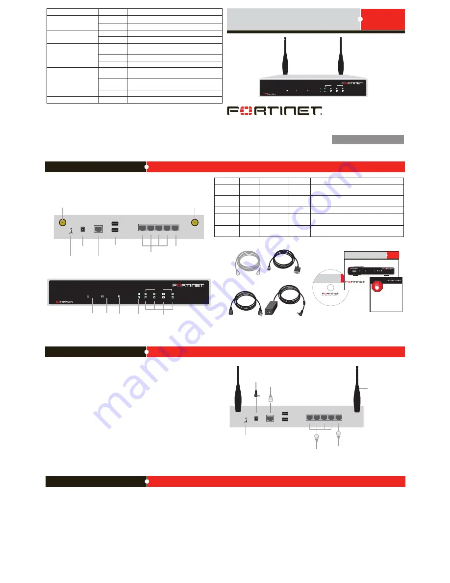
FortiGate-30B
QuickStart Guide
STATUS
WAN
INTERNAL
1
2
3
POWER
USB
REGISTER
WAN
POWER
STATUS
INTERNAL
3
2
1
LINK / ACTIVITY
10/100
WLAN
30B
4
Straight-through Ethernet cable connects
to Internet (public switch or router).
Attach the antenna to the
antenna mounts.
Straight-through Ethernet cables connect
to computers on internal network
Power cable
connects to power supply
Ground
RJ-45 to DB-9 serial cable
connects to management computer
1
2
3
USB
CONSOLE
WAN
C 12
4
1
2
3
USB
CONSOLE
4
WAN
C 12
Power
Connection
RJ-45 Serial
Connection
USB
Ground
Antenna mount
WAN
Internal Interface,
switch connectors
1,2,3,4
Back
Power
LED
Status
LED
WAN
Interface
Internal
Interface
WLAN
LED
Front
Antenna mount
WAN
POWER
STATUS
INTERNAL
3
2
1
LINK / ACTIVITY
10/100
WLAN
30B
4
Package Contents
Connect the FortiWiFi unit to a power outlet and to the internal and external networks.
•
Affix the rubber feet to the underside of the FortiWiFi unit, and attach the antennas to
the antenna mounts on the back of the FortiWiFi unit.
•
Place the unit on a stable surface. Make sure the FortiWiFi unit has adequate air flow
for cooling.
•
Place the FortiWiFi unit in a prominent location within a room for maximum coverage,
rather than in a corner.
•
Be aware of the construction of your environment, concrete and metal walls can hamper
signal strength.
•
Keep the AP and wireless devices at least 10 feet away from appliances such as micro-
wave ovens and cordless phones.
FortiWifi-30B
01-30007-97324-20090520
QuickStart Guide
LED
State
Description
Power
Green
The unit is on.
Off
The unit is off.
Status
Green
On during start up or reboot.
Off
Normal operation.
WLAN
Flashing
Green
Flashing when enabling Wireless LAN port.
Green
Wireless LAN port is up.
Off
Wireless LAN port is down.
Link / Activity
Green
The correct cable is in use and the connected equip
-
ment has power.
Flashing
Green
Network activity at this interface.
Off
No link established.
10/100
Green
The interface is connected at 100 Mb.
Connector
Type
Speed
Protocol
Description
Internal
RJ-45
10/100 Base-T Ethernet
4-port switch connection to up to four devices on the
internal network.
WLAN
Antenna
802.11
b/g
Wireless connections to LAN.
WAN
RJ-45
10/100 Base-T Ethernet
Connection to the Internet.
CONSOLE
RJ-45
9600 bps
8/N/1
RS-232
serial
Optional connection to the management computer.
Provides access to the command line interface (CLI).
USB
USB
USB
Optional connection for USB key for firmware backup
and installation.
Web-based manager
The web-based manager is an easy to use management tool.
Use it to configure the administrator password, the interface and default gateway addresses,
and the DNS server addresses.
Requirements:
•
An Ethernet connection between the unit and management computer.
•
A web browser such as FireFox or Internet Explorer on the management computer.
Command Line Interface (CLI)
The CLI is a full-featured management tool. Use it to configure the administrator password,
the interface addresses, the default gateway address, and the DNS server addresses. To
configure advanced settings, see the Tools and Documentation CD-ROM.
Requirements:
•
The RJ-45 to DB9 serial connection between the unit and management computer.
•
A terminal emulation application (HyperTerminal for Windows) on the management
computer.
Configuration Tools


