

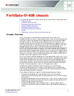


FortiGate-5140B chassis
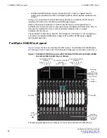
FortiGate-5140B front panel
FortiGate-5140B Chassis Guide
01-500-156415-20151104
11
•
The location of the four hot-swappable front replaceable cooling fans (behind the
cooling fan bay cover)
•
The location of the front-replaceable air filter (behind the air intake bezel).
•
The Electrostatic discharge (ESD) socket, used for connecting an ESD wrist band
when working with the chassis
•
Chassis handles.
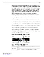
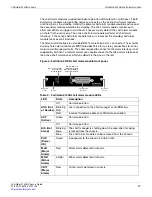
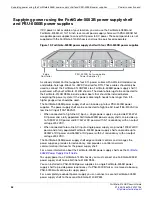
Figure 2: FortiGate-5140B chassis back panel (cable tray not shown)
Do not operate the FortiGate-5140B chassis with open slots on the front panel. For
optimum cooling performance and safety, the chassis slots must contain a
FortiGate-5000 series board or an air baffle slot filler. For the same reason, all cooling
fan trays and the air filter should be installed while operating the chassis. As well both
PEMs must be installed in the back of the chassis.
Power
Entry Module A
S
helf
Manager
s
S
helf Alarm
Module
s
Power
Entry Module B
Cha
ss
i
s
ground
connector
(green)
-48/-60 VDC
nom (black)
-48/-60 VDC
nom (black)
RTN
(red)
RTN
(red)
E
S
D
s
ocket
RTM
s
lot number
s
RTM
air baffle
s
lot cover
s