


-11-
FES101E6
User Manual
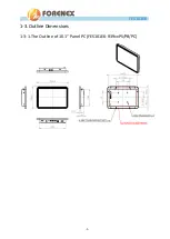
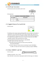
2-2.
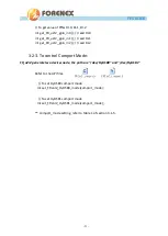
DC Power Connector
On front panel, external secondary power input.
Pin Assignment:
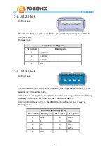
2-3.
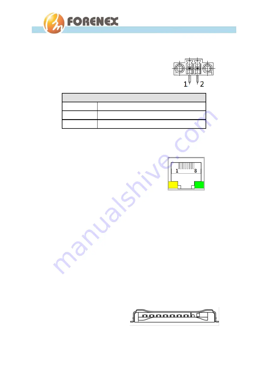
Gigabit Ethernet Port with PoE+
On front panel.
The RJ45 port that supports high-speed Gigabit Ethernet and conform to the 802.3at
specification. The Inner 802.3at PoE+ board is Powered Device (PD) controller and
switching regulator for high power IEEE 802.3at(25W) and 802.3af(12W) applications.
The integrated 8-pin Gigabit Ethernet port is using an 8 Position 8 Contact (8P8C)
receptacle connector (commonly referred to as RJ-45).
The Gigabit Ethernet port (RJ-45 port) has two individual LED
indicators located on the front side to show:
-
Active LED is blinking in green color means activity of data flow
IN or OUT of the device.
-
Link LED is in Red color means devices is operating in speeds 10/100Mbps.
Link LED is in Green color means devices is operating in speeds 1000Mbps.
2-4.
Micro SD/SDHC card Slot
On Front panel.
Adapted card size(11 x 15 x 1.0 mm)
Micro SD/SDHC card slot without spring and enable the SD storage up to 32GB size.
Connector: ( Terminal Block-2P/Male )
Pin number
Description
1
GND
2
DC12V
Содержание FES101E6
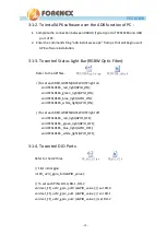
Страница 4: ...4 FES101E6 User Manual 3 2 2 To control DIO Ports 20 3 2 3 To control Comport Mode 21...
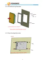
Страница 9: ...9 FES101E6 User Manual 1 3 2 Panel Mounting Illustration 1 3 3 Clips Mounting Illustration...
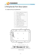
Страница 10: ...10 FES101E6 User Manual 2 Peripherals Port Description 2 1 External IO port placement...
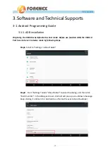
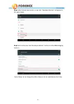
Страница 17: ...17 FES101E6 User Manual Step5 Scroll to Settings USB Then Scroll to USB ADB HOST Set USB3 0 as ADB...


