Model 914-HDE User Manual
Focal Technologies Corporation
2-1
A Moog Inc. Company
Document Number: 914-0601-00 Rev. 4.0
Setup Check List
The purpose of this section is to provide a check list that can be followed to setup 914-HDE systems both
physically and through electronic configuration. Details regarding each step can be found in the manual via the
referenced section links.
1. Expansion cards:
a. 914-VDX: Set dip switch to appropriate setting, refer to
Section 5.1.6
i. The (bottom) card closest to the 914-HDE should be set to OFF, OFF (Expansion 1).
2. Mounting cards:
a. 4 mm minimum clearance under the 914-HDE.
b. 16.15 mm (nominal) standoffs of 2-56 type between cards.
c. Thermal gap material to provide conductive cooling to an enclosure should be placed under
the 914-HDE.
d. Refer to
Section 7.1
3. Connect console to remote via LC to LC fiber jumper. For short links, attenuation is required. 10 dB is
the suggested minimum attenuation in the fiber link. For flux budget calculations refer to
Section 3.8.1.
4. Connect the diagnostic port on console 914-HDE to a local COM port of a computer running the 914
Diagnostic GUI. Refer to
Section 4.0
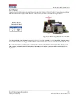
5. Connect the 914-HDE to a DC power supply with 5 V to 12 V power. Refer to
Section 3.2
. Verify all
system voltages in the 914 Diagnostic GUI.
6. Configure all cards via Diagnostic GUI:
a. Configure console HDE
i. Serial protocol. Refer to
Section 4.1.2
ii. Ethernet auto-negotiate settings. Refer to
Section 4.1.3.
b. Configure console VDX
i. Remote vs console. Refer to
Section 5.1.7
ii. Video direction. Refer to
Section 5.1.7
iii. Serial protocol. Refer to
Section 5.1.8
c. Configure remote HDE
i. Serial protocol. Refer to
Section 4.1.2
ii. Ethernet auto-negotiate settings. Refer to
Section 4.1.3.
d. Configure remote VDX
i. Remote vs console. Refer to
Section 5.1.7
ii. Video direction. Refer to
Section 5.1.7
iii. Serial protocol. Refer to
Section 5.1.8
e. Turn the power off, wait 10 seconds and power up again. Confirm settings using the 914
Diagnostic GUI.
7. Connect video, Ethernet and serial as required. Verify plug status and activity in the 914 Diagnostic
GUI.
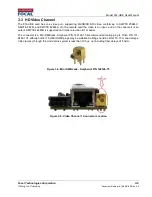
a. HD Video
– Refer to
Section 3.3
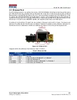
b. Ethernet
– Refer to
Section 3.5
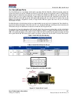
c. Serial Ports
– Refer to
Section 3.4
d. Composite Video
– Refer to
Section 5.1.2
8. Perform bench level testing to verify links. Refer to troubleshooting
Section 10.0
9. Install cards in system, ensure good thermal contact via mounting hardware, thermal gap pads, and
heat spreaders. Refer to
Section 7.3
10. Verify and monitor the FPGA and SFP temperatures and voltages during operation. All values should
remain in green.


