background image


ZIPThaw™ 202 System User Manual 


Fremon Scientific, Inc.

 5726 La Jolla Blvd., Suite 304, La Jolla, CA 92037USA  


P

age 16 of 43


FDA


CLEARED

ZipThaw

 20 2 System

User Manual


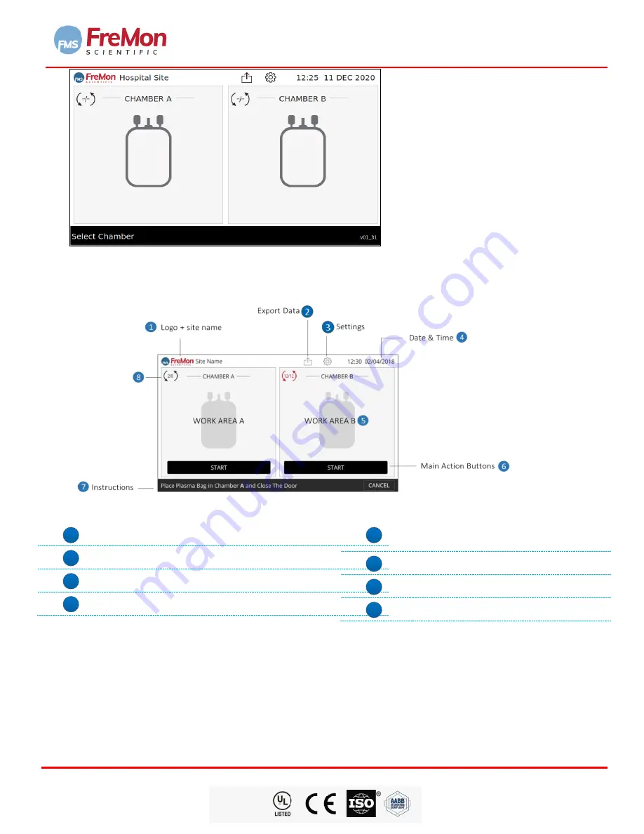
FIGURE 11.   HOME SCREEN 


7.4     MAIN SCREEN DESCRIPTION   


FIGURE 12.   Home Screen 


1


FreMon logo+ site name 

2


Export Data. 

3


Settings. 

4


Date & Time. 

5


Work Area A+B  - the user main area 
interaction.


6


Main Action Buttons.


7


Instructions for active Chamber.


8


Number of ZipSleeve

TM

 uses indicator. 

7.5     SETTINGS 


Pressing  the  “

Settings

” 

icon  will  open  the  settings  login  screen. 

The  following  screens  are  for  the  device 

administrator and technical support use only. 


Entering the 

Settings Screen

 requires an administrator password. The administrator will have a default password 

(

45253

, factory default) that can be changed in the setting screen. 


Содержание ZipThaw 202

Страница 1: ...Fremon Scientific Inc 5726 La Jolla Blvd Suite 304 La Jolla CA 92037USA Doc No 447000 UM 01 01 Page 1 of 49 FDA CLEARED ZipThaw 202 System User Manual ...

Страница 2: ... System User Manual Copyright FreMon Scientific Inc Revision 09 Revision date Jan 2022 Fremon Scientific Inc 5726 La Jolla Blvd Suite 304 La Jolla CA 92037 USA Approved By Signature Date Farideh Bischoff PhD Chief Executive Officer Moni Shavit Chief Technical Officer William Davey VP Product Management Design 01 12 2022 1 14 2022 1 14 2022 ...

Страница 3: ...r CMC 8 4 1 4 ZipSleeveTM 8 4 1 5 Power Supply 8 4 2 ZIPTHAW202TM FRONT VIEW 9 4 3 ZipThaw202TM Rear View 9 4 4 ZipSleeveTM 10 4 5 How does it work 10 4 6 Default Temperature Setting 10 4 7 Labeling and Symbols 11 4 7 1 Rear Panel 11 4 7 2 Symbols used in this User Manual 11 4 8 Compliance with FCC 47 C F R Part 18 12 5 CONTRAINDICATIONS 12 6 SAFETY ADVICE 12 7 OPERATION 13 7 1 Device placement an...

Страница 4: ...put 23 7 9 STARTING A THAWING CYCLE 24 7 9 1 Loading Frozen Plasma Bag Into a ZipSleeve 24 7 9 2 Loading the ZipSleeve Into the Chamber 25 7 9 3 Selecting MELT or THAW Option 27 7 9 4 Starting 27 7 9 5 Intentional Thawing Stop 27 7 9 6 Running Thawing Using the Second Chamber B 28 7 10 End of Thawing Cycle 29 7 11 Timeout Thawing Cycle 29 8 EXPORTING DATA 31 8 1 Exporting Data Structure 31 9 POWER...

Страница 5: ...9 FIGURE 20 Adding a New User Screen 20 FIGURE 21 Adding a New User 20 FIGURE 22 Warming Cushion Replacement Screen 21 FIGURE 23 Cushion Replacement Reminder Screen 21 FIGURE 24 Select Chamber from Home Screen 22 FIGURE 25 Barcode Insert Data Screen 22 FIGURE 26 Manual Entry Data Screen 23 FIGURE 27 Mandatory Fields Data Entry Error and Bipassing Data Entry 23 FIGURE 28 Home Screen After Data Entr...

Страница 6: ...rd Blood except for Research Use Only 3 2 IMPORTANT These instructions use the following pictograms symbols and words to highlight warnings and special advice WARNING A warning alerts the user to the possibility of a danger to persons associated with misuse of the device CAUTION A caution alerts the user to the possibility of a problem with the device which could pose danger to property the device...

Страница 7: ...rol Rate Thawing W Watt GUI Graphical User Interface V Volt EIS Electronic Information Systems Amp Ampere Min Minute s HMI Human Machine Interface FEC Front End Controller Chamber Where the product bag is processed AC Alternating Current SOM System on a Module computer CMC Chamber Module Controller TCM Thawing Chamber Module SMP System Management Processor BIT Built in Test a diagnostics program t...

Страница 8: ... protection is accomplished by utilizing an independent temperature sensor that shuts down power in case of cushion overheating 4 1 2 SYSTEM MANAGEMENT PROCESSOR SMP System Management Processor unit SMP that can control up to 4 CMCs The SMP is a high level CPUs that controls and monitors system function drives a touch screen GUI module and external memory media 4 1 3 CHAMBER MODULE CONTROLLER CMC ...

Страница 9: ...ientific Inc 5726 La Jolla Blvd Suite 304 La Jolla CA 92037USA Page 9 of 43 FDA CLEARED ZipThaw 202 System User Manual 4 2 ZIPTHAW 202TM FRONT VIEW FIGURE 1 ZIPThawTM 202 front view 4 3 ZIPTHAW 202TM REAR VIEW FIGURE 2 ZIPThawTM 202 rear view ...

Страница 10: ... The plasma frozen bag temperature is monitored by the ZipSleeveTM temperature sensor RFID and will signal the system to stop heating once the sensor temperature reading reaches the Target Temperature of 31 C 87 8 F for the THAW option or no more than 15 C 59 0 F for the MELT option while the ZipThawTM system controls the agitation mechanism to ensure homogeneous mixing and heat distribution 4 6 D...

Страница 11: ... LABELING AND SYMBOLS 4 7 1 REAR PANEL FIGURE 4 ZIPThawTM 202 Label 4 7 2 SYMBOLS USED IN THIS USER MANUAL No Symbol Description 1 CE MARK 2 ATTENTION CONSULT ACCOMPANYING DOCUMENTS 3 WASTE OF ELECTRICAL AND ELECTRONIC EQUIPMENT WEEE COMPLIANCE SYMBOL 4 MANUFACTURER 5 AUTHORIZED REPRESENTATIVE IN THE EUROPEAN UNION 6 FUSE 7 PI LOT NUMBER 8 CATALOG NUMBER LOT CAT ...

Страница 12: ... not limited to red blood cells hematopoietic progenitor cells umbilical cord blood previously thawed Cryoprecipitate AHF Platelets or Granulocytes There are no known contraindications for thawing or heating blood products 6 SAFETY ADVICE WARNING Read the instructions contained in this user manual and any other user documentation before using the device This device is class I electrical equipment ...

Страница 13: ...es of anesthetic substances with air oxygen or nitrous oxide whose flashpoint is below 50 C 122 F 7 OPERATION 7 1 DEVICE PLACEMENT AND POWER CONNECTION Ensure there is enough space for the ZipThawTM 202 to be placed on the bench or cart Leave at least 10cm 4 between the rear side of the ZipThawTM 202 and a wall to allow easy access to power ON OFF main switch located as part of the IEC socket Leav...

Страница 14: ...wer on the back of the device and unplug the Power Cord for 5 minutes Restart device If problem persists contact your FMS distributor or contact us at info fremonscientific com and check our web site https fremonscientific com for assistance FIGURE 8 SYSTEM ERROR POP UP SCREEN 7 3 2 BIT FAILURE During the self diagnostic tests the system will determine whether both Chambers are functioning or one ...

Страница 15: ...d will have a grayed out graphic appearance FIGURE 10 HOME SCREEN WITH CHAMBER ERROR 7 3 3 SYSTEM RESET RECOVERY In case that the system defaults to an unexpected Reset mode upon successful BIT the home screen will appear and the system will recover in to pre thawing state see 7 7 Fig 24 Note It is the user s discresion to start a new thawing cycle using these bags or discarding them To continue a...

Страница 16: ...te Time 5 Work Area A B the user main area interaction 6 Main Action Buttons 7 Instructions for active Chamber 8 Number of ZipSleeveTM uses indicator 7 5 SETTINGS Pressing the Settings icon will open the settings login screen The following screens are for the device administrator and technical support use only Entering the Settings Screen requires an administrator password The administrator will h...

Страница 17: ...replacement settings see section 7 6 below FIGURE 13 Login to the Settings Screen Note If the administrator password is forgotten the password may only be reset by a certified technician Upon entering the correct administrator password and pressing OK the following setting screen will appear FIGURE 14 Settings Screen 7 5 1 KEYS DESCRIPTIONS Pressing this key will revert back to the home screen wit...

Страница 18: ...he language will change and the chosen flag will be displayed Note Default Language is English represented by the American flag icon and is currently the only language that is actively available 7 5 3 SELECTING TEMPERATURE UNIT The administrator can select which temperature unit will be displayed i e Celsius or Fahrenheit by touching the corresponding radio button Figure 16 Temperature Units 7 5 4...

Страница 19: ... touch the Time field The time format is 24 00 Use the keyboard to enter the current time Figure 18 Setting Date Time Note If the typed information is incorrect the field will be marked red 7 5 6 ENABLING AUDIO To enable audio alerts turn Sound ON or OFF by sliding the corresponding switch ON OFF Figure 19 Enabling Audio 7 5 7 ADDING NEW USER Touching the Users field enables typing a new user name...

Страница 20: ... and the user can either scan the ID or type it using the displayed keyboard To confirm new user press the new name and ID will be added to the list 7 5 8 EDITING USER LIST Mark the Users i e touching the drop down list will be displayed To delete a user name from the list press the X icon on the right side of the user ID To add a newly added user press the ENTER key When finished editing the whol...

Страница 21: ...y the software The manufacturer recommends replacement as soon as feasibly possible May continue to use if needed as long as the cushions are not damaged or leaking Date of last cushion change sets itself to the current date as the date the cushions were last changed Next Replacement Date sets itself to the current date pluse the designated replacement interval below Replacement Interval Max Cycle...

Страница 22: ... INSERT THAWING DATA Data can be entered Using the built in barcode reader Manually typing the data 7 8 1 BARCODE DATA ENTRY Place the plasma bag in front of the barcode reader and aim the red beam to the upper barcode field 1 of the plasma bag label Once you hear a beep move to next bar code field i e 2 3 4 one at a time Verify that the correct data was entered especially the donor identification...

Страница 23: ...e DIN Up to 16 characters ABO RhD 4 characters Product Code 8 characters Expiration Date time 10 characters 7 8 3 BY PASSING DATA ENTRY Once data is entered To accept data entry and return to the Home Screen press the OK key To cancel and return to the home screen press CANCEL If OK was pressed but a mandatory field was not filled the system will mark the unfilled field for the user to complete th...

Страница 24: ...hown below FIGURE 28 Home Screen after Data Entry Chamber A Procede to loading frozen plasma unit into the ZipSleeve Section 7 8 1 below 7 9 STARTING A THAWING CYCLE 7 9 1 LOADING FROZEN PLASMA BAG INTO A ZIPSLEEVE 1 Place the frozen plasma bag inside a ZipSleeveTM 2 Insert the frozen bag with the label facing the clear side of the ZipSleeveTM Note Once the ZipThawTM system verifies that a valid Z...

Страница 25: ...e 3 hangers inside the Chamber Note Please note that the ZipSleeveTM can be loaded only in the orientation indicated by the slots in the hard plastic strip at the top of the ZipSleeveTM If the plasma bag was frozen with the ports end of the bag folded over the cycle time may be extended For larger volume units that were frozen folded you can do a cycle and stop after several minutes unload straigh...

Страница 26: ...han or equal to 8 before the START key is enabled If the ZipSleeveTM was used 8 times the system will display the following screen FIGURE 31 Replace ZipSleeveTM due to Number of Uses Screen Replace the ZipSleeveTM as described above 7 8 1 7 8 2 Upon Chamber door closing with a valid ZipSleeveTM the GUI will display the following screen FIGURE 32 Home Screen With Chamber A Loaded Start Options Melt...

Страница 27: ...a units for a much faster throughput This is useful for building and maintaining a working inventory of refrigerated liquid plasma 7 9 4 STARTING Press one of the 2 start options MELT of THAW to start the thawing process The following GUI will be displayed FIGURE 33 Chamber A Thawing Screen Note Agitation will start automatically once the thawing cycle begins Note During a Thaw or Melt cycle you m...

Страница 28: ...t To confirm thawing cycle stop press OK or to continue the thawing cycle press Cancel 7 9 6 RUNNING THAWING USING THE SECOND CHAMBER B The ZipThawTM system enables thawing in both Chambers simultaneously but independent of each other Simply tap on the Chamber B icon the screen will be updated FIGURE 35 Thawing Cycle Chamber A Running Chamber B Ready Screen Repeat 7 8 1 to 7 8 4 with respect to Ch...

Страница 29: ...le will alert the user i e sound LED light will flicker once and again for 1 second after 5minutes Operator must remove the thawed product from ZipThaw202 as soon the cycle completes Once removed immediately close the Chamber Door 7 11 TIMEOUT THAWING CYCLE The ZipThawTM system has a timeout mechanism that stops the thawing cycle in cases where the thawing process doesn t reach the target temp i e...

Страница 30: ...Export Data icon the following GUI will be displayed FIGURE 38 Export Data Screen When entering the screen the user will Scan Enter his her User ID barcode will be lit when entering the screen and shut after scanning or after the user types his ID and press enter Export data button will be idle until the ID is entered The user then connects a USB drive and presses EXPORT FILES A pop up with a prog...

Страница 31: ... 02 error 03 error 04 Bag TEMP at 00 30 Bag TEMP at 01 00 Bag TEMP at 01 30 Bag TEMP at 60 00 Log number between 1 1999 Thawing date MM DD YYYY Thawing start time Thawing end time when cycle stopped or finished 24 00 format User ID as inserted in the insert data screen 24 00 format Bag ID as inserted in the insert data screen From START until end of thawing Cycle 33 C Green ICON Extra Time of bag ...

Страница 32: ...n Press CANCEL to cancel and return to the previous screen Press YES to confirm standby mode The system will enter a standby mode Pressing the standby mode button will wake the system and a power up process will be initiated as described above see Section 7 3 9 2 TURN OFF MODE To turn the ZIPThawTM 202 off completely i e disconnect the power press the On Off switch located at the back of the devic...

Страница 33: ...he Main power on the back of the device 2 Unplug the Power Cord for 30 seconds 3 Restart device Chamber A Error Use Chamber B Error Messages Error found during system BIT Testing Chamber A malfunction YES A System Error Pop Up message Chamber A will be disabled 1 Pressing OK will close the popup 2 Follow IFU regarding Technical Support assistance Chamber B Error Use Chamber A Error Messages Error ...

Страница 34: ... Close Chamber Door Warning Message Chamber Door A is not properly closed NO 1 A System Pop Up message 2 System will disable Chamber A thawing operation until the Chamber door is closed properly 1 Pressing OK will close the popup message 2 Close Chamber A Door Properly Door B is Open Please Close Chamber Door Warning Message Chamber Door A is not properly closed NO 1 A System Pop Up message 2 Syst...

Страница 35: ...tem Pop Up a message 2 The system pause thawing at Chamber A 1 Close Chamber Door 2 Pressing YES will resume thawing 3 Pressing NO will abort the thawing cycle Chamber Door B Opened Resume Thawing Warning Message Indicating that Chamber B Door was opened during thawing cycle YES 1 A System Pop Up a message 2 The system pause thawing at Chamber B 1 Close Chamber Door 2 Pressing YES will resume thaw...

Страница 36: ...stem Pop Up a message 2 The incorrect fields will be marked red 1 Pressing OK will close the popup message 2 Re Enter correct passwered Incorrect Data Please Re enter Data OK Warning Message Indicating that date and time were not filled correctly NO 1 A System Pop Up a message 2 The incorrect fields will be marked red 3 Pressing OK will close the popup message 4 Re Enter correct date time The Devi...

Страница 37: ...ing Message Indicating that the downloading of data failed NO A System Pop Up a message 1 Pressing OK will close the popup Media Memory Full Warning Message Indicating that the Media disk on key is full NO A System Pop Up a message 1 Pressing OK will close the popup SYSTEM ON OFF Turning OFF ZIPThaw Are You Sure Warning Message Indicating that the ON OFF push button was pressed NO A System Pop Up ...

Страница 38: ...h or caustic agents Do not get any spray or liquid inside the ZipThaw202 11 3 DISPLAY CLEANING To clean the device touch screen please use Lens Wipes containing water Isopropyl Alcohol Detergent and Anti Static 11 4 EMPTING THE SPILL TRAY The spill Trays should be emptied cleaned and disinfected on an as needed basis such as when a plasma unit is seen to have leaked inside the ZipSleeve or if a wa...

Страница 39: ...nd Dual Core Cortex A9 1GB DDR3 1GB SLC NAND and 64GB eMMC Full HD 1080p video encoding decoding capability Vivante GPU providing 2D 3D acceleration Chamber Control STMicroelectronics STM32L073 MCU 32BIT 192KB Interface Network USB USB 2 0 OTG USB 2 0 Host Memory Bank Internal for 2 000 thawing records Internal Power Supplies Medical grade isolating power supply Input 100 240Vac maximum rated curr...

Страница 40: ...ication equipment In case of an interruption beware of such a device in the vicinity Use of the system with any accessory transducer or cable other than those specified may result in increased EMISSIONS or decreased IMMUNITY than those specified The system should not be used adjacent to or stacked with other equipment If adjacent or stacked use is necessary the system should be observed to verify ...

Страница 41: ...ctrical fast transient burst IEC 61000 4 4 2 kV for power supply lines 1 kV for input output lines 2 kV for power supply lines 2 kV for input output lines Mains power quality should be that of a typical commercial or hospital environment Surge IEC 61000 4 5 1 kV differential mode 2 kV common mode 1 kV differential mode 2 kV common mode Mains power quality should be that of a typical commercial or ...

Страница 42: ...itters as determined by an electromagnetic site survey a should be less than the compliance level in each frequency range b Interference may occur in the vicinity of equipment marked with the following symbol NOTE 1 At 80 MHz and 800 MHz the higher frequency range applies NOTE 2 These guidelines may not apply in all situations Electromagnetic propagation is affected by absorption and reflection fr...

Страница 43: ...utput power of transmitter W Separation distance according to frequency of transmitter m 150 kHz to 80 MHz 80 MHz to 800 MHz 800 MHz to 2 5 GHz 0 01 0 12 0 12 0 23 0 1 0 37 0 37 0 74 1 1 17 1 17 2 33 10 3 69 3 69 7 38 100 11 67 11 67 23 33 For transmitters rated at a maximum output power not listed above the recommended separation distance d in meters m can be estimated using the equation applicab...

Отзывы: