background image

FS-MG4

Digital Proportional Radio Control System

8

5.5  Mode switching


This function is for reusing the ST.TRIM and ST.D / R buttons for different channels (see [5.3 

Trims], [5.4 D/R).

Function setting:

 Under normal power-on condition, press the BIND button twice (within 1S) to switch between 
mode 1 and mode 2. By default, mode 1 is used.
Mode 1: R.LED is always on. G.LED is off. ST.TRIM is for CH1 trim. ST.D/R is for CH1 servo 
adjustment. TH.TRIM is for CH2 throttle trim. TH.D/R is for CH2 throttle servo adjustment.
Mode 2: R.LED and G.LED are flashing alternately. ST.TRIM is for CH3 trim. ST.D/R is for CH3 
servo adjustment. TH.TRIM is for CH4 trim. TH.D/R is for CH4 servo adjustment.

      This function dictates what the receiver will do in the event that it loses signal from the 
transmitter, this includes servo position etc. 

Setup:

When  the  transmitter  is  switched  on  in  normal  communication  state,  keep  the  channel  to  be 
set  at  the  position  of  the  failsafe  setup,  and  press  and  hold  the  BIND  button  for  3S.  The  G.LED 
flashes  for  2S,  indicating  that  the  setting  is  successful.  That  is,  when  the  receiver  cannot 
receive the signal, it will output the set failsafe value.

Note: The fail-safe function has no default set at the factory and as such must be set manually. 

If  no  failsafe  setting  has  been  set,  then  the  receiver  will  not  output  anything  when  signal  is 

lost. 

5.6 Failsafe 

      Beginner mode is designed for people new to the hobby. 
      In this mode the throttle will be limited to 50 percent, The channel range defaults to 
1250~1500~1750us.

Setup: 
To switch between beginner and normal modes,first press and hold the channel 4 button and  
Turn the handwheel to the bottom counterclockwise ,then turn on the transmitter . 

Note: By default, the system is set to normal mode. The GLED will flash slowly for 3 seconds 
during power on if the system is set to beginner mode. 

5.7 Beginner Mode

Содержание FS-MG4

Страница 1: ...FS MG4 Copyright 2021 Flysky Technology co ltd USER MANUAL Digital Proportional Radio Control System...

Страница 2: ...sers In order to ensure your safety and the safety of others read this manual carefully before using this product If you encounter any problem during use refer to this manual first If the problem pers...

Страница 3: ...g 5 4 2 LED 5 4 4 Stick Calibration 6 4 5 Power Off 6 5 System Functions 7 5 1 Channel Description 7 5 2 Channel Reverse 7 5 3 Trims 7 5 4 D R 7 5 5 Mode switching 8 5 6 Failsafe 8 5 7 Beginner Mode 8...

Страница 4: ...y of you and others do not operate in the following places Near any site where other radio control activity may occur Near power lines or communication broadcasting antennas Near people or roads On an...

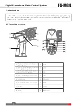
Страница 5: ...nner players to use 2 1 Transmitter overview 1 Traversing handwheel 35 degrees on each side CH1 9 ST D R 2 Throttle button 25 degrees in front and 12 5 degrees at rear CH2 10 TH D R 3 Push button swit...

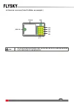
Страница 6: ...iver overview Take FS R4B as an example Note To ensure the best signal quality make sure that the antenna is mounted perpendicular to the model body in an upright position CH1 CH2 CH3 CH4 S LED Sticke...

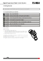
Страница 7: ...the battery or expose to strong shocks or vibrations Danger Always store the battery in a cool dry place Danger Do not use the battery if damaged Battery Type AAA Battery Installation 1 Open the batt...

Страница 8: ...l the receiver s LED will flash slowly and the transmitter s LED will remain solid after being rebooted Note When binding put the transmitter into bind mode first then the receiver 4 1 Power On Howeve...

Страница 9: ...flash twice 2 Calibrate wheel Turn the wheel completely clockwise then completely counterclockwise When calibration is completed the R LED will be off 3 Trigger calibration Pull the trigger back then...

Страница 10: ...s for CH2 throttle and can be multiplexed as Trims of CH4 For multiplexing switching mode see 5 5 Mode Switching Adjustment range 120us 120us ST TRIM TH TRIM counterclockwise adjustment to increase th...

Страница 11: ...ansmitter is switched on in normal communication state keep the channel to be set at the position of the failsafe setup and press and hold the BIND button for 3S The G LED flashes for 2S indicating th...

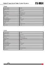
Страница 12: ...According to battery type Low Voltage Warning 4 2V Antenna Type Built in single antenna Data Interface No Temperature Range 10 60 Humidity Range 20 95 Online Update No Color Black size 118 73 145mm w...

Страница 13: ...ce PWM Temperature Range 10 60 Humidity Range 20 95 Online Update No weight 3 4g size 34 18 4 11 5mm Certification CE FCC Product Model FS R4P PWM Channels 4 RF 2 4GHz ISM 2 4GHz Protocol ANT Distance...

Страница 14: ...11 7 Package Contents Transmitter 1 FS MG4 Receiver 1 FS R4B...

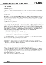
Страница 15: ...ation is subject to the following two conditions 1 This device may not cause harmful interference and 2 This device must accept any interference received including interference that may cause undesire...

Страница 16: ...via private persons is for free The owner of old appliances is responsible to bring the appliances to these collecting points or to similar collection points With this little personal effort you cont...

Страница 17: ...Copyright 2021 Flysky Technology co ltd www flysky cn com Release date 2021 04 22 CE FCC ID N4ZMG400...

Отзывы: