background image

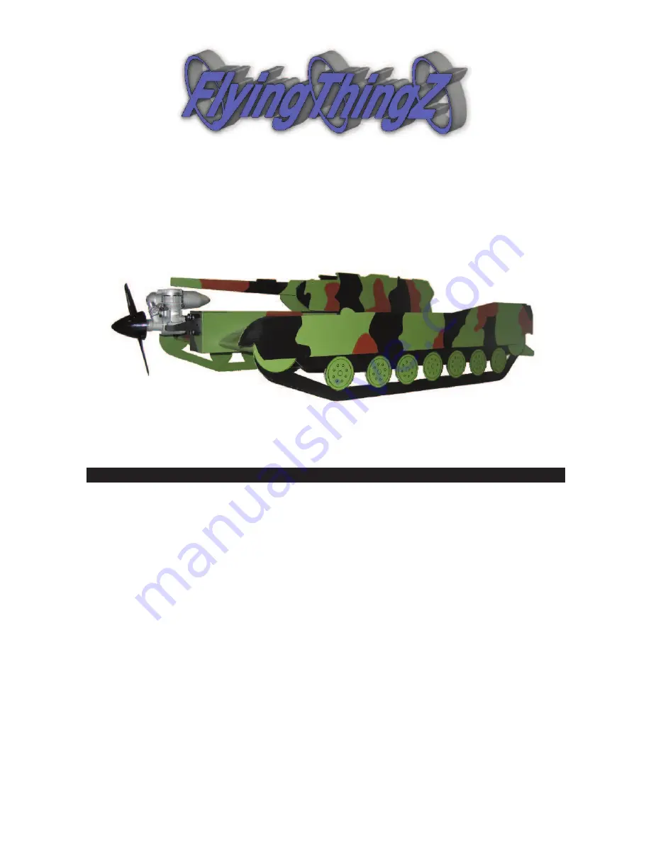
M1A1 Flying Tank

A Sport Scale Flying Military Tank

The M1A1 Flying Tank is fun and easy to build. We have done all the hard work for you. It can easi-

ly be framed up and covered in a weekend. While it may look a little bit different, the construction

techniques used are the same as most other airplanes. The average modeler will have no problem. You

will find top quality Laser Cut balsa, plastic and plywood, as well as beautiful CNC Cut foam cores

and parts! It is the ultimate high tech kit!

Low speed flying is great, with huge elevons and tons of surface area, it will crawl along with

full control and amazing stability. To speed up all you need to do is give it gas! It flies smooth, sta-

ble, and responds great. Most say that it flies like a low wing sport plane. Landings are breeze, just

lower the throttle and she’ll settle in on her own. All in all you can't find a plane that gets you more

attention and is as fun to fly.

Copyright © 2010

Kit# FTZ3015

Specifications

Wingspan:

24"

Wing Area:

864 sq in

Weight:

7 lbs.

Radio:

4 Channel w/ Elevon Mixing

Engine:

.46 - .61 two-stroke / .53 - .71 four-stroke

Содержание M1A1 Flying Tank

Страница 1: ... cores and parts It is the ultimate high tech kit Low speed flying is great with huge elevons and tons of surface area it will crawl along with full control and amazing stability To speed up all you need to do is give it gas It flies smooth sta ble and responds great Most say that it flies like a low wing sport plane Landings are breeze just lower the throttle and she ll settle in on her own All i...

Страница 2: ...al 4 Kit Contents 4 Additional Requirements 5 Required Tools and Adhesives 5 Fuselage Assembly 6 Preparing the Foam 1 0 Wing Assembly 1 0 Elevon Assembly 1 3 Coroplast Parts Assembly 1 3 Final Assembly 1 3 Radio Setup 1 6 Control Throws CG 1 7 Pre Flight Checklist 1 7 Flight Characteristics 1 8 2004 AMA Safety Code 1 8 ...

Страница 3: ... IS NOT A TOY IF MISUSED IT CAN CAUSE SERIOUS BODILY HARM AND DAMAGE TO PROPERTY FLY ONLY IN OPEN AREAS PREFERABLY AT AMA www modelaviation com APPROVED SITES FOLLOW ALL INSTRUC TIONS INCLUDED WITH YOUR RADIO AND ENGINE You must assemble the model according to the instructions Do not alter or modify the model as doing so may result in an unsafe or unstable aircraft In a few cases the instructions ...

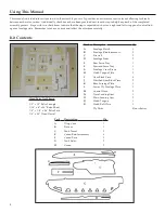
Страница 4: ...carefully Kit Contents Part Description Qty A Fuselage Hatch 1 B Fuselage Reinforcements 2 C Firewall 2 D Fuselage Sides 2 E Rear Servo Tray 1 F Forward Servo Tray 1 G Fuselage Cross Brace 1 H Hatch Tongue Plate 2 I Gear Block Piece 6 J Notched Gear Block Piece 2 K Rear Fuselage Plate 1 L Lower Ply Fuselage Plate 1 M Control Horn 2 N Nose Landing Gear 1 O Main Landing Gear 2 Q Hatch Tongue 1 R Hat...

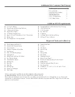
Страница 5: ...ors Wax Paper Paper Towels Ruler Mixing Sticks Threadlock Denatured Alcohol Rotary Tool or Dremel Router Attachment for Rotary Tool or Dremel Rubber Bands Dead Center Engine Mount Locator Hex Wrench Set Drill Bits 1 16 3 32 1 8 5 64 and 1 2 bits Electric Drill Unless a specific glue is specified use your best judgement when joining parts CA WILL EAT FOAM DO NOT USE CA TO BOND ANY PARTS TO FOAM Mos...

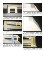
Страница 6: ... up with the notches in the front of the reinforcement Again use a square to assure it s at a perfect 90 deg angle to the fuselage The small hole on the firewall should be on the top left when laid out as shown in the photo above A6 Using clamps glue the two fuselage sides together The firewall and cross brace should line up with the notches on the other side of the fuselage reinforcement Make sur...

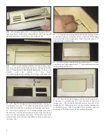
Страница 7: ...e rear servo tray at this time it is only being used as a spacer A10 Size and cut a hatch tongue plate and glue it to the notch es on the back of the fuselage Sand the edges flush with the sides of the fuselage Sand the rearward part of the hatch tongue plate to match the angle of the fuselage as shown in the image above A11 Glue the rear fuselage hatch plate to the back of the fuse lage Sand the ...

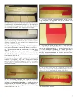
Страница 8: ... Glue the balsa sticks to the sides of the fuse the rear servo tray and the fuselage cross brace Cut the balsa stick at the notches on the servo tray you ll need these notches to mount your radio gear later A17 Reinstall the fuselage hatch and flip the fuselage around so that the bottom is facing up Draw a line onto the fuselage hatch across the hatch tongue plate Extend the lines about 1 2 along ...

Страница 9: ...se follow the manufacturer s instructions on using their material for covering A24 Lay a piece of the precut vinyl shaped like the fuselage on your workbench Place the fuselage onto the vinyl and cut slits into the vinyl at the corners of the fuselage Fold the corners over onto the fuselage and trim any excess Leave approximately 1 8 to 1 4 overlap Cut out the opening on the bottom of the fuselage...

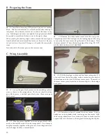
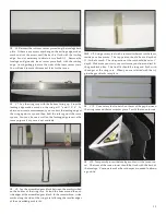
Страница 10: ...ces together to form one gear block with a notch in the middle as shown in the image above Use clamps to keep the assembly together as the glue sets Once the glue has set sand all edges flush for a smooth finish C3 Remove the foam center insert from the wing core Temporarily install the fuselage into the leading edge of the wing core and lay the foam center along the side of the fuselage Place the...

Страница 11: ...d gear block between the marks scribed on the bottom of the wing core Extend the lines around the out side edges of the assembled gear block In the same fashion scribe marks along the side of the wing core following the smaller edges of the assembled gear blocks C9 Using a rotary tool with a router attachment cut the foam inside your line marks The top portion should be at a depth of 11 16th of an...

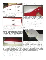
Страница 12: ... slits into the vinyl to follow the contour of the wing Repeat for the other half of the wing bottom The two pieces of vinyl covering should leave an overlap in the middle approxi mately 1 4 C18 On the wings top scribe a mark 11 3 4 from the side of the wing on both the leading and trailing edge Using another piece of vinyl cut at 27 lay the covering along the marks on top of the wing Squeeze out ...

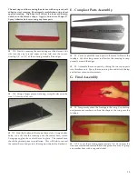
Страница 13: ...e control horn cutout Using epoxy glue the control horns in place The control horn should be painted prior to installation This will help to conceal the control horns and protects them against the fuel and exhaust E Coroplast Parts Assembly E1 Cover or paint the canon parts in the same fashion as the fuselage Cut slits along curves to allow for the covering to wrap properly around the edges E2 Ass...

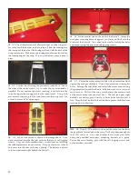
Страница 14: ...ning The battery is placed in the compartment right behind the firewall G6 Scribe a center line on the front of the firewall Center the nose gear mounting brackets against your line and flush with the bottom of the firewall Use a dead center tool to create pilot holes and mount using the provided self tapping screws G7 Center the motor mount on the scribed center line flush against the nose gear b...

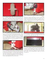
Страница 15: ...kets Insert the nose gear through the control horn the first bracket the space then the top bracket The top of the wire should butt up against the bottom of the motor mount Do not change the length of the nose wire it should bring the nose slightly higher than the rest of the model G12 Using 4 40 rod make a bend outlined in the image above as a sample Align the rod with the control horn and mark a...

Страница 16: ...hrough the holes on the turret and through the canon Tie it all together by screwing the oppo site side in place Apply a dab of oil on the screw to avoid cracking the carbon rod H Radio Setup H1 Turn on the transmitter then the receiver and center the trims If necessary remove and adjust the control clevises or the servo control horns to obtain a centered position H2 Make certain that the controls...

Страница 17: ...nna is fully extended and there is a strain relief in place to prevent it from being pulled from the receiver housing Do not cut any excess antenna wire Use a threadlocking compound on all metal to metal fasteners such as nuts bolts and set screws Add a few drops of oil to the wheel axles so that they spin freely Make sure all hinges are secure Reinforce holes for wood screws with CA where appropr...

Страница 18: ...cs any device that explodes burns or propels a projectile of any kind including but not limited to rockets explosive bombs dropped from models smoke bombs all explosive gases such as hydrogen filled balloons ground mounted devices launching a projectile The only exceptions permitted are rockets flown in accordance with the National Model Rocketry Safety Code or those perma nently attached as per J...

Страница 19: ...n RC racing event whether or not an AMA Rule Book event is one in which model aircraft compete in flight over a pre scribed course with the objective of finishing the course faster to determine the winner A In every organized racing event in which contestants callers and officials are on the same course 1 All officials will be off the course except for the starter and their assistant 2 On the cour...

Страница 20: ...FlyingThingZ Inc 2075 Grandview St Oceanside CA 92054 www flyingthingz com support flyingthingz com ...

Отзывы: