


PG9602™ OPERATION AND MAINTENANCE MANUAL
© 2011 Fluke Calibration
Page
46
Select
<2control>
,
<3loadall>
to clear the AMH and load all the masses on to
the piston. This is the condition used to remove and install the AMH. In this
state, the AMH retains no masses.
Select
<2control>
,
<1unloadall>
to clear the AMH and unload all the masses
from the piston. In this state, the AMH retains all the masses.
3.7.2.5
Making and Breaking Reference Vacuum with AMH
When making and breaking a reference vacuum under the bell jar, it is important
that the AMH mass manipulation actuators also be exposed to the correct
pressure. The correct pressure is vacuum in absolute mode and atmosphere in
gauge mode.
If the AMH is to be operated with a vacuum in the bell jar, a vacuum supply must
be connected to the drive vacuum connection quick connector so that the AMH
actuators (mass lifter, mass selector pins) are evacuated when they are not
pressurized. See Section 2.3.1.5.2 for information on correctly connecting the
drive vacuum supply to AMH.
When using the AMH in absolute mode, and if the drive vacuum supply sleeve
valve is being used, it must be set to the VACUUM position just before
establishing the reference vacuum. This position closes the circuit, isolating it
from atmosphere.
When operating with atmosphere in the bell jar, and if the drive vacuum supply
sleeve valve is being used, it must be set to the GAUGE position so that the
AMH actuators vent to atmosphere.
Caution
Failure to supply vacuum to the AMH’s drive vacuum port
before establishing a reference vacuum may cause unexpected
operation of the binary mass selector pins which could result in
damage to the AMH mass handler and or masses (see Section
3.7.1). NEVER plug the AMH vent port.
3.7.2.6
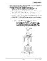
Accessing the Piston-Cylinder Module with AMH
To access the piston-cylinder module in a PG9000 Platform with the AMH
installed requires that the AMH first be removed and then the mass set must be
removed.
First, remove the AMH mass handler as described in Section 3.7.2.2.
Then, remove the AMH mass set following the instructions in Section 2.3.1.4 in
reverse order.
Once the AMH mass handler and mass set are removed, the piston-cylinder
module can be accessed and removed. (see Section 2.3.2.)
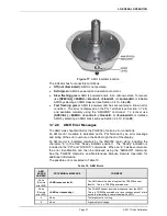
3.7.2.7
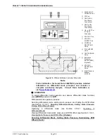
AMH Indicator LED
There is a green indicator LED located on the front of the PG9000 base plate
beside the spirit level (see Figure 17). This is the AMH status indicator.
Содержание PG9000 Series
Страница 10: ...PG9602 OPERATION AND MAINTENANCE MANUAL 2011 Fluke Calibration Page X Notes...
Страница 128: ...PG9602 OPERATION AND MAINTENANCE MANUAL 2011 Fluke Calibration Page 118 Notes...
Страница 164: ...PG9602 OPERATION AND MAINTENANCE MANUAL 2011 Fluke Calibration Page 154 Notes...
Страница 188: ...PG9602 OPERATION AND MAINTENANCE MANUAL 2011 Fluke Calibration Page 178 Notes...
Страница 192: ...PG9602 OPERATION AND MAINTENANCE MANUAL 2011 Fluke Calibration Page 182 Notes...


