


PG9602™ OPERATION AND MAINTENANCE MANUAL
© 2011 Fluke Calibration
Page
18
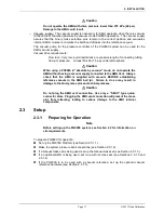
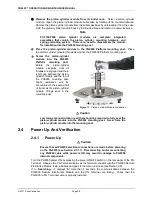
2.3.1.1
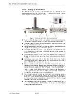
Setting Up the Platform
The PG9000 Platform consists of the PG9000 Base, the PG9000 Remote
Electronics Module and the PG Terminal. To set up the PG9000 Platform
reference the call outs and proceed as follows:
Figure 5.
Setting up the PG9602 electrical connections
Place the PG9000 Base on the work surface in the desired orientation.
Though the rear panel is usually in the back, any orientation can be used.
Place the PG9000 Terminal and PG9000 Remote Electronics Module near
the base in the desired locations.
Connect the PG9000 Terminal to the PG9000 Remote Electronics Module
using the 25-pin cable supplied with the PG Platform.
Connect the PG9000 Temperature - Humidity Probe to the PG9000 Remote
Electronics Module either directly to the back panel or via the supplied TH
Probe extension cable.
Connect the PG DRIVER connectors on the PG9000 Remote Electronics
Module and PG9000 Base using the 15-pin cable supplied with the PG
Platform.
Connect electrical power (100 to 240 VAC, 50/60 Hz) to the PG9000
Terminal using the power cable supplied. Any grounded power cable with a
standard IEC320-313 connection may be used.
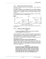
If an automated pressure generation / control component is being used,
establish communications between the automated pressure generation /
control component and the PG9000 Platform by connecting a 9-pin RS232
cable between the COM1 port of the generation / control component to the
PG9000 Platform COM3 port and setting up PG9000 to use an automated
pressure generation / control component (see Section 3.10.9). It is important
that the COM port settings on both instruments match.
If an external barometer is being used, establish communications between
the barometer and the PG9000 Platform by connecting the barometer’s
RS232 port to the PG9000 Platform COM2 port and setting up PG9000 to
read and use the external barometer (see Section 3.12.5.4). Set the external
barometer head height (see Section 3.12.3.3).
Level the platform using the two leveling feet and the bubble level mounted
on the front of the platform. The front foot is stationary and not intended to
be part of the leveling adjustment.
Содержание PG9000 Series
Страница 10: ...PG9602 OPERATION AND MAINTENANCE MANUAL 2011 Fluke Calibration Page X Notes...
Страница 128: ...PG9602 OPERATION AND MAINTENANCE MANUAL 2011 Fluke Calibration Page 118 Notes...
Страница 164: ...PG9602 OPERATION AND MAINTENANCE MANUAL 2011 Fluke Calibration Page 154 Notes...
Страница 188: ...PG9602 OPERATION AND MAINTENANCE MANUAL 2011 Fluke Calibration Page 178 Notes...
Страница 192: ...PG9602 OPERATION AND MAINTENANCE MANUAL 2011 Fluke Calibration Page 182 Notes...


