


PG9602™ OPERATION AND MAINTENANCE MANUAL
© 2011 Fluke Calibration
Page
162
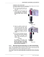
indicate the mass is to be loaded onto the piston. A value of “0” for the MAIN masses
indicates that no main masses will be loaded. Press [ENT] to activate the mass load change.
Press
[SPECIAL]
,
<7cal>
,
<5Pposition>
,
<2cal>
.
The prompt
<Hold piston at max down stop>
appears. Check that the pressure under the
piston is completely vented and press
[ENT]
. The lower travel position is now defined.
The prompt
<Hold piston at max up stop>
appears. Without changing the mass load,
generate a pressure under the piston great enough to ensure that the piston will go
completely to the top stop. This requires a pressure equivalent to a mass load of 18 kg.
For example, if a 10 kPa/kg piston-cylinder is being used, apply enough pressure that is
at least equivalent to 180 kPag. Press
[ENT]
. The upper travel position is now defined.
Process is complete. Use
[SPECIAL]
, select
<7cal>
,
<5Pposition>
,
<1view>
to verify
that piston position is +4.5 mm when fully up and -4.5 mm
when fully down.
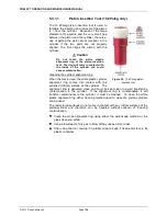
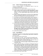
5.2.3
Drive Belt Replacement
Periodic replacement of the drive system belts may be necessary to retain maximum
performance of the rotational engagement system. Over time the belts tend to dry out or
develop a sheen on the surface that makes them less able to grip the mass carrying bell. A
common maintenance effort is to remove the belt and wash with soap and water to partially
restore the ability for the belt to grip the mass bell. If this does not yield the desired results
then it may be necessary to replace the drive belts
Note
A set of spare drive belts is included in the accessories delivered with the
PG9000 Platform.
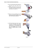
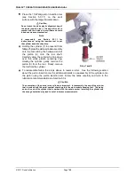
To remove the drive belts:
Using a 3 mm hex tool, remove the three screws on the lower flange of the pulley plate.
Do not remove the screws on the upper flange (inner diameter) as the pulleys are
attached to the underside of the plate. The pulley plate is located directly around the
mounting post.
Remove the two drive belts and replace them with the new ones. Take care to clean the
new belts with soap and water to remove any remaining mold release to ensure good
contact with the mass bell. It is suggested to wear gloves when handling the drive belts
to avoid transferring oils to the drive belt surfaces.
Realign the notched pulley with the pins on the drive motor.
Replace the pulley plate and three screws.
Engage the drive system to ensure proper operation.
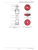
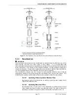
5.3
Piston-Cylinder Modules: Disassembly, Cleaning, and
Maintenance
PURPOSE
To disassemble and reassemble piston-cylinder modules, clean the piston-cylinder elements, evaluate
cleaning results, lubrication of piston-cylinder module, and recalibration of piston-cylinder effective area.
PRINCIPLE
The PG9602 uses the same gas operated piston-cylinder modules as used with PG7102 and PG7601 –
identified as PC-7100/7600-xx. These piston-cylinders are interchangeable between the three platforms.
Note
A piston-cylinder delivered with a PG7102 or PG7601 is compatible with PG9602,
however its metrological properties must be recertified for operation to determine
uncertainty at higher mass loads.
Содержание PG9000 Series
Страница 10: ...PG9602 OPERATION AND MAINTENANCE MANUAL 2011 Fluke Calibration Page X Notes...
Страница 128: ...PG9602 OPERATION AND MAINTENANCE MANUAL 2011 Fluke Calibration Page 118 Notes...
Страница 164: ...PG9602 OPERATION AND MAINTENANCE MANUAL 2011 Fluke Calibration Page 154 Notes...
Страница 188: ...PG9602 OPERATION AND MAINTENANCE MANUAL 2011 Fluke Calibration Page 178 Notes...
Страница 192: ...PG9602 OPERATION AND MAINTENANCE MANUAL 2011 Fluke Calibration Page 182 Notes...


