


OF-500 OptiFiber Certifying OTDR
Technical Reference Handbook
1-26
Changing the Logo on the HOME Screen
The tester’s
HOME
screen shows the Fluke Networks logo
by default.
To change the logo on the
HOME
screen:
1
Register your tester with Fluke Networks to receive a
registration key. See “Registration” on page 1-2 for
details.
2
Use a graphics application to create a graphic with
the following format:
•
Dimensions: 240 x 60 pixels maximum.
•
Colors: 128 colors maximum, with an indexed color
palette.
•
File format: Save the graphic as an 8-bit bitmap file
(.bmp) or an 8-bit Portable Networks Graphic file
(.png).
Note
The graphics application may list 256 colors with
the 8-bit setting; however, if your graphic uses
only 128 or fewer colors, it should work in the
tester.
3
Press
F
;
then select
Enable OptiFiber Options
.
4
On the
OPTIFIBER OPTIONS
screen, highlight
CUSTOM LOGO
; then press
t
.
5
Enter the software key in the
CUSTOM LOGO
key
box; then press
s
.
6
Connect the tester to the PC via the serial or USB
port.
7
In LinkWare select
Utilities
>
OptiFiber Utilities
>
Custom Logo
. Locate and select the .bmp or .png
logo file; then click
Open
.
8
Restart the tester to see the new logo.
Note
If the logo’s format is not valid, the tester deletes
the logo and uses the default logo.
To restore the Fluke Networks logo, select
Utilities
>
OptiFiber Utilities
>
Restore Default Logo
; then restart the
tester
Содержание OF-500 OptiFiber
Страница 12: ...OF 500 OptiFiber Technical Reference Handbook x ...
Страница 18: ...OF 500 OptiFiber Technical Reference Handbook xvi ...
Страница 27: ...Getting Acquainted Powering the Tester 1 1 9 ajt20f eps Figure 1 1 Battery Pack Features ...
Страница 29: ...Getting Acquainted Verifying Operation 1 1 11 ajt56f eps Figure 1 2 Removing the Module ...
Страница 46: ...OF 500 OptiFiber Certifying OTDR Technical Reference Handbook 1 28 ...
Страница 95: ...Using the OTDR Running the OTDR Test 3 3 21 ajt33f eps Figure 3 12 Connecting the OTDR to Spooled Cable ...
Страница 133: ...Using the ChannelMap Function Running the Test 4 4 3 ajt55f eps Figure 4 2 ChannelMap Test Connections ...
Страница 136: ...OF 500 OptiFiber Certifying OTDR Technical Reference Handbook 4 6 ...
Страница 148: ...OF 500 OptiFiber Certifying OTDR Technical Reference Handbook 6 4 ajt61f eps Figure 6 2 Changing the Connector Adapter ...
Страница 192: ...OF 500 OptiFiber Certifying OTDR Technical Reference Handbook 6 48 ...
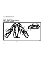
Страница 196: ...OF 500 OptiFiber Certifying OTDR Technical Reference Handbook 7 4 ajt03f eps Figure 7 2 Using the Visual Fault Locator ...
Страница 254: ...OF 500 OptiFiber Certifying OTDR Technical Reference Handbook 11 36 ...
Страница 256: ...OF 500 OptiFiber Certifying OTDR Technical Reference Handbook ...
Страница 261: ...Loss Test Methods Method A A 2 B B 3 ajt58f eps Figure B 1 Method A A 2 Reference and Test Connections singlemode shown ...
Страница 263: ...B 5 ajt59f eps Figure B 2 Method B A 1 Reference and Test Connections singlemode shown Loss Test Methods Method B A 1 B ...
Страница 265: ...Loss Test Methods Method C A 3 B B 7 ajt60f eps Figure B 3 Method C A 3 Reference and Test Connections singlemode shown ...
Страница 272: ...B 14 OF 500 OptiFiber Certifying OTDR Technical Reference Handbook ...
Страница 274: ...OF 500 OptiFiber Certifying OTDR Technical Reference Handbook C 2 ...
Страница 282: ...OF 500 OptiFiber Technical Reference Handbook 8 ...


