9100A-017
7-19
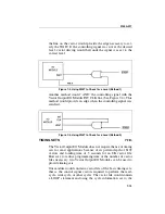
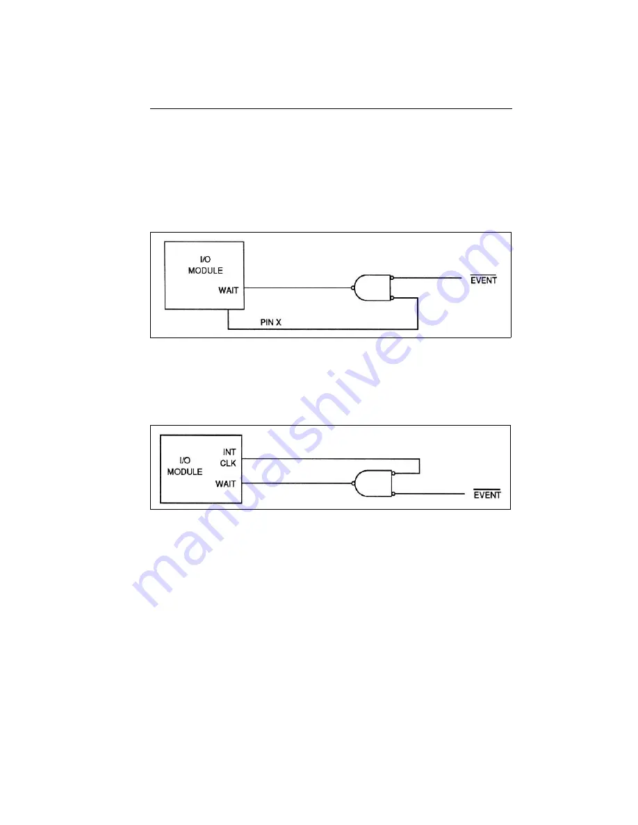
the line on the vector would provide the edge necessary to sat-
isfy the WAIT. If the controlling signal was not at the desired
level, vector driving would halt until the signal was set to the
correct level.
Figure 7-3. Using WAIT to Check for a Level (Method 1)
Another method would “AND” the controlling signal with the
Vector Output I/O Module INT CLK line (See Figure 7-4). This
method would provide an edge when the controlling signal was
satisfied.
Figure 7-4. Using WAIT to Check for a Level (Method 2)
TIMING SETS
7.18.
The Vector Output I/O Module does not require the use of timing
sets for most applications because of its pattern depth of 8192
vectors and loading time of 3 seconds for an 8K vector file.
However, to reduce programming time or the number of vector
files necessary, two Vector Output I/O Modules can be used to
provide timing sets.
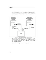
One module would contain a vector file of the basic timing sets;
that is, the control signal vectors required to perform the read-
cycle, writecycle, or other cycles. The vector file would contain
a LOOP statement enclosing the cycle information set to the
Содержание 9100A Series
Страница 6: ...vi ...
Страница 8: ...viii ...
Страница 10: ...x ...
Страница 14: ...9100A 017 1 4 ...
Страница 24: ...9100A 017 3 6 ...
Страница 44: ...9100A 017 5 4 ...
Страница 58: ...9100A 017 6 14 ...
Страница 83: ...A 1 Appendix A New TL 1 Commands ...
Страница 84: ...9100A 017 A 2 ...
Страница 87: ...clockfreq 3 For More Information The Overview Of TL 1 section of the Programmer s Manual ...
Страница 88: ...clockfreq 4 ...
Страница 91: ...drivepoll 3 For More Information The Overview Of TL 1 section of the Programmer s Manual ...
Страница 92: ...drivepoll 4 ...
Страница 104: ...vectordrive 4 ...
Страница 107: ...vectorload 3 For More Information The Overview Of TL 1 section of the Programmer s Manual ...
Страница 108: ...vectorload 4 ...
Страница 116: ...9100A 017 C 2 ...
Страница 117: ...9100A 017 C 3 ...
Страница 118: ...9100A 017 C 4 ...

