Maintenance
Accuracy Performance Tests
4
4-33
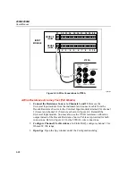
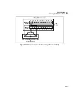
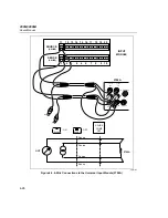
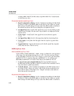
Testing of the Digital Input/Output signal lines can be done through the
RS-232 port (using HyperTerminal or other communication program) or through
the Fluke DAQ software. Either method can be used. The Digital Input/Output
Test checks the 20 Digital I/O lines through the Digital I/O connector module for
correct operation. Measurements of the signal lines may be made using a
oscilloscope or a voltmeter. See Figure 2-7 for the layout of the DIO module
connector.
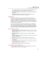
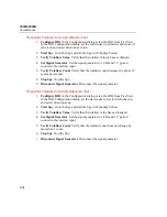
Fluke DAQ Totalizer Count Test
1.
Go to Spy Window
Go to the Spy Window.
2.
Set Instrument Number
Set the instrument number to the BCN number of
the instrument and set the category as totalizer.
3.
Start Spy
Start the Spy with the play button.
4.
Verify Totalizer Value
Verify that the totalizer value is set to zero.
5.
Set Signal Generator
Set the signal generator to 10 Hz and 1 V pp and
connect to the totalizer input.
6.
Verify Totalizer Count
Verify that the totalizer count increases by about 10
counts per second in a positive direction.
7.
Stop Spy
Stop the Spy.
8.
Disconnect Signal Generator
Disconnect the signal generator.
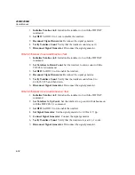
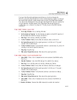
Fluke DAQ Totalizer Count and Enable Test
1.
Select DIO
Click on the Communication icon and select the DIO from the
TreeView.
2.
Disable Totalizer
Select the DIO channel 0 to disable the totalizer.
3.
Start Spy
Go to the Spy and start the Spy with the play button.
4.
Verify Totalizer Value
Verify that the totalizer value has not changed.
5.
Set Signal Generator
Set the signal generator to 10 Hz and 1 V pp and
connect to the totalizer input.
6.
Verify Totalizer Count
Verify that the totalizer count does not change.
7.
Stop Spy
Stop the Spy.
8.
Disconnect Signal Generator
Disconnect the signal generator.
9.
Select DIO
Click on the Communication icon and select the DIO from
TreeView.
10.
Enable Totalizer
Deselect the DIO channel 0 to enable the totalizer.
Содержание 2680A
Страница 8: ......
Страница 14: ...2680A 2686A Users Manual vi ...
Страница 20: ...2680A 2686A Users Manual 1 2 ...
Страница 98: ...2680A 2686A Users Manual 2 62 ...
Страница 196: ......
Страница 228: ...2680A 2686A Users Manual A 32 ...
Страница 236: ...2680A 2686A Users Manual C 4 ...
Страница 242: ...2680A 2686A Users Manual D 6 ...
Страница 274: ...2680A 2686A Users Manual 6 ...


