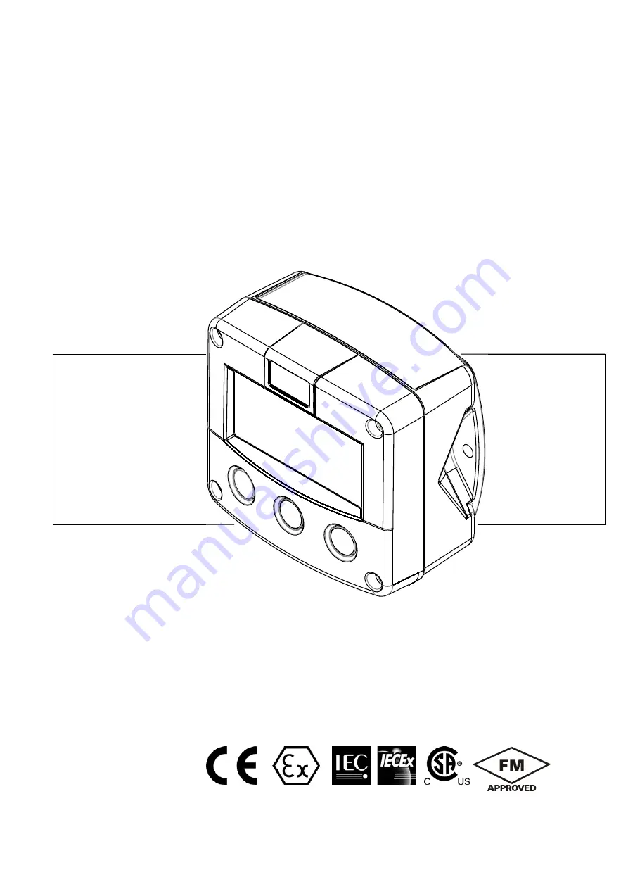
F040-T
TEMPERATURE INDICATOR
Signal input sensor: PT100
Options: Intrinsically Safe.
F-Series - Field mounted indicators for safe and hazardous areas. More info: www.fluidwell.com/fseries
Страница 1: ...F040 T TEMPERATURE INDICATOR Signal input sensor PT100 Options Intrinsically Safe F Series Field mounted indicators for safe and hazardous areas More info www fluidwell com fseries...
Страница 2: ...disposed of according to local regulations regarding waste electronic equipment If a battery is present in this product it should be disposed of separately The separate collection and recycling of you...
Страница 3: ...cedures which if not performed correctly may lead to personal injury a safety hazard or damage of the F040 T or connected instruments A caution indicates actions or procedures which if not performed c...
Страница 4: ...4 Sensor 12 5 Others 13 4 Installation 14 4 1 General directions 14 4 2 Installation surrounding conditions 14 4 3 Dimensions Enclosure 15 4 4 Installing the hardware 17 4 4 1 Introduction 17 4 4 2 T...
Страница 5: ...iguration of the unit The F040 T has been designed to be implemented in many types of applications For that reason a SETUP level is available to configure your F040 T according to your specific requir...
Страница 6: ...apter describes the daily use of the F040 T This instruction is meant for users operators 2 2 CONTROL PANEL The following keys are available Fig 2 Control Panel Functions of the keys This key is used...
Страница 7: ...tically Temperature is displayed on the upper line of the display and the measuring unit on the bottom line When is shown then the value is too high to be displayed Low battery alarm When the battery...
Страница 8: ...manual are to be observed Ensure that the measuring system is correctly wired up according to the wiring diagrams The housing may only be opened by trained personnel Take careful notice of the Safety...
Страница 9: ...low the word SETUP at the bottom of the display The number is a combination of two figures The first figure indicates the function group and the second figure the sub function Additionally each functi...
Страница 10: ...to select in the other direction When data is altered but ENTER is not pressed then the alteration can still be cancelled by waiting for 20 seconds or by pressing ENTER for three seconds the PROG proc...
Страница 11: ...played temperature The following units can be selected C F K Alteration of the measurement unit will have consequences for operator and SETUP level values Please note that the Span has to be adapted a...
Страница 12: ...l settings are stored In this mode power consumption is extremely low To wake up the unit again press the SELECT key twice 4 SENSOR NR OF WIRES 41 The PT100 element used can have 2 3 or 4 wires Do sel...
Страница 13: ...formation in the case of a serious breakdown or to assess the suitability of your model for upgrade considerations SERIAL NUMBER 53 For support and maintenance it is important to have information abou...
Страница 14: ...ccidental contact is no longer assured when the housing cover is removed or the panel cabinet has been opened danger from electrical shock The housing may only be opened by trained personnel Take care...
Страница 15: ...G9 PG9 30mm 30mm 22 5mm M20 x 1 5 M16 x 1 5 M16 x 1 5 30mm 30mm 22 50mm M20 x 1 5 22 5mm M20 x 1 5 M20 x 1 5 25mm 25mm 22 5mm 1 2 NPT 0 9 3x 1 2 NPT 0 12 0 12 0 9 HA HM HN HO HP HT HU 6 x M12 12mm 12m...
Страница 16: ...K HK back box flat bottom HE HF HG HH D 12mm 12mm 12mm 24mm 24mm 36mm 36mm 14mm 17mm 22 5mm 30mm 30mm D 16mm D 20mm 0 9 D 22mm 0 866 22 5mm 25mm 25mm D 20mm D 20mm D 16mm HC 75 mm 2 95 118 mm 4 65 104...
Страница 17: ...lied with the 115 230V AC power supply type PM The green yellow wire between the back casing and removable terminal block may never be removed Fig 7 Grounding aluminum enclosure with option PM 115 230...
Страница 18: ...cy Terminal 5 6 POWER SUPPLY UNIT TYPE PX To power the unit an internal battery can be used type PB and or an external DC power supply of 8 30V DC type PX Connect the to terminal 5 and the to terminal...
Страница 19: ...RE 4 3 Fig 9 Overview of terminal connectors F040 T PF PM and options REMARKS TERMINAL CONNECTORS Terminal GND 01 02 POWER SUPPLY only available with type PF PM OPTION SENSOR SUPPLY Terminal GND 01 02...
Страница 20: ...stalled in accordance with the Atex directive 94 9 EC and the product certificate KEMA 05ATEX1168 X For installation under IECEx scheme this intrinsically safe device must be installed in accordance t...
Страница 21: ...ut PT100 Intrinsically Safe Possible static hazard Do not rub KEMA 05ATEX1168 X Tamb IP67 II 1 G Ex ia IIC T4 II 1 D Ex iaD 20 IP 65 67 T 100 C IECEx KEM 08 0006X Ga Ex ia IIC T4 Ex iaD 20 IP 65 67 T...
Страница 22: ...on example IIA IIB and IIC application F040 T PX XI ZB TERMINAL CONNECTORS F0 series 4 5 Common ground Main supply 9 10 Common ground Supply backlight HAZARDOUS AREA SAFE AREA Power supply For example...
Страница 23: ...F or expose contents to water INSTRUCTION SHEET BATTERY REPLACEMENT FW LiBAT 001 Replacement Instructions Safety Instructions Fluidwell bv The Netherlands www fluidwell com sales fluidwell com FW LiB...
Страница 24: ...above 90 annual mean It is the users responsibility to take all precautions to dehumidify the internal atmosphere of the F040 T in such a way that no condensation will occur for example by placing dr...
Страница 25: ...HU Type HV Type HZ GRP enclosures Type HD Type HE Type HF Type HG Type HJ Type HH Type HK ABS enclosure Type HS Dimensions 130 x 120 x 75mm 5 10 x 4 72 x 2 95 LxHxD IP67 NEMA4X Drilling 2x PG9 1x M20...
Страница 26: ...A to G T4 Class I zone 0 AEx ia IIC T4 Explosion proof Type XF ATEX approval ref EX II 2 GD EEx d IIB T5 Weight appr 15kg Dimensions of enclosure 350 x 250 x 200mm 13 7 x 9 9 x 7 9 LxHxD Environment E...
Страница 27: ...When the alarm flag starts to blink an internal alarm condition has occurred Press the select button several times to display the 4 digit error code The codes are 0001 irrecoverable display data erro...
Страница 28: ...are version 3 high current 27 installation 14 intrinsic safety 20 IP classification 14 keys 6 low current 27 low battery 7 main function 9 maintenance 24 manual version 3 model 13 operational 6 operat...
Страница 29: ...es 16 Fig 7 Grounding aluminum enclosure with option PM 115 230V AC 17 Fig 8 Overview of terminal connectors F040 T PB PX and options 18 Fig 9 Overview of terminal connectors F040 T PF PM and options...
Страница 30: ...HF040TEN_v0402_03 Atex_IECEx_CSA_FM Page 30 NOTES...
Страница 31: ...HF040TEN_v0402_03 Atex_IECEx_CSA_FM Page 31 NOTES...
Страница 32: ...ENSOR Enter your settings here 41 nr of wires 2 42 filter 01 off 5 OTHERS Enter your settings here 51 model F040 T F040 T F040 T 52 software version 03 ____ ____ 03 ____ ____ 03 ____ ____ 53 serial nu...