Flowserve NAF 791290 Скачать руководство пользователя страница 1

1

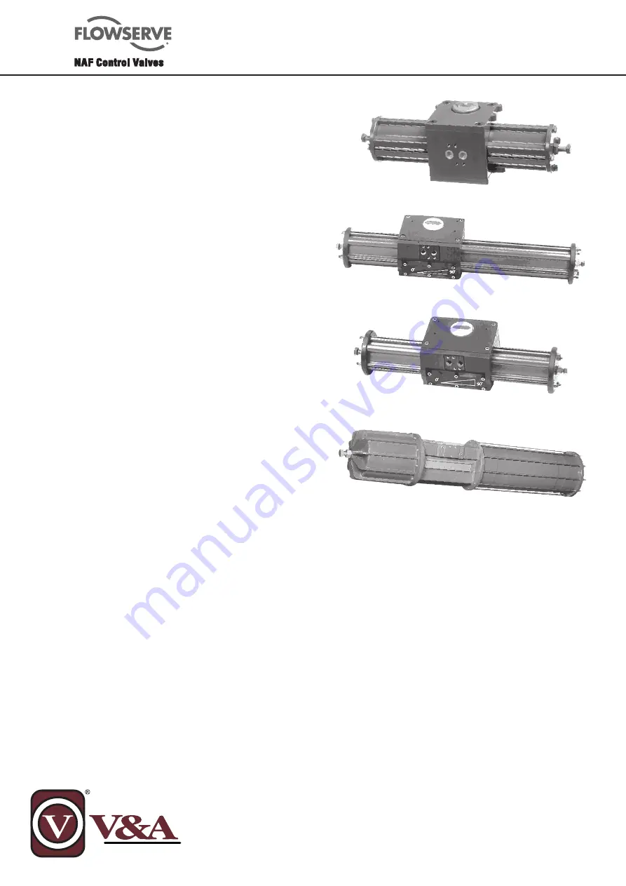
NAF-Turnex pneumatic actuators

NAF 791290/92/94, sizes 0, 1-3 and 4-5

Maintenance instructions and spare parts list

Fi 74.59(3)GB

05.12

General

 ...........................................................

1


Maintenance ..................................... 2

Dismantling ........................................................................ 2.1

Checking for damage and wear .......................................... 2.2

To change the piston rod bearings, size 0 .......................... 2.3

To change the piston rod seal, sizes 1-3

and 4-5 .............................................................................. 2.4

To change the PTFE-coated bushes ................................... 2.5

Assembly ........................................................................... 2.6

Actuator with spring return .................... 3 

Conversion of a double-acting actuator ............................. 3.1

To dismantle and assemble the spring-

return unit .......................................................................... 3.2

To dismantle the spring-return unit .................................... 3.3

To assemble the spring-return unit .................................... 3.4

Accessories ...................................... 4  

Stem sleeves, sizes 1-3 ...................................................... 4.1

End position indication ....................................................... 4.2

Fitting the end position sensor ........................................... 4.2.1

Junction  box ..................................................................... 4.3

Solenoid valves .................................................................. 4.4

Valve positioner ................................................................. 4.5 

Manual operation device .................................................... 4.6


Spare parts ....................................... 5

Part number of spare parts kits .......................................... 5.1

Spare parts kits, sizes 0 and 1-3 ........................................ 5.2

Spare parts kits, sizes 4-5 .................................................. 5.3 

Parts list .......................................... 6

Double-acting actuator, sizes 0 and 1-3 ............................. 6.1 

Single-acting actuator, sizes 0 and 1-3 .............................. 6.2

Single- or double-acting actuators, sizes 4-5 ..................... 6.3

Contents

1. General

The actuators are designed to withstand a long period of 

continuous operation at high loading, normally without 

the need for servicing. 
Air or an inert gas must be used as the actuating medium. 

The air must be dried and thoroughly cleaned to prevent  

wear of the cylinder bores, pistons and sealing rings. 

Oil mist lubrication of the actuating medium is not 

recommended. The maximum permissible pressure of the 

actuating medium is 0.8 MPa (8 bar) and the maximum 

permissable temperature is 80°C.
From the operating viewpoint, the actuator can be 

installed in any position. However, it must not be 

subjected to excessive radiant heat, vibrations or 

other adverse circumstances that could damage its 

components. 

The actuator delivered from NAF AB is in fully operational 

condition. For particulars of the correct connection/

commissioning, refer to the commissioning instructions 

Fi 74.562 iGB.

These actuators normally require little or no maintenance. 

However, after a long period of service, certain parts 

may become worn or damaged, and will then have to be 

replaced. 

To minimize the time needed for overhaul or repair, 

it is advisable to keep a suitable stock of spare parts. 

These are available as individual components, but it is 

economically preferable to purchase the spare parts kits 

recommended by NAF, the compositions of which are 

matched to different overhaul levels. 

Size 0

Size 4 - 5

Size 1 - 3

Содержание NAF 791290

Страница 1: ...peration at high loading normally without the need for servicing Air or an inert gas must be used as the actuating medium The air must be dried and thoroughly cleaned to prevent wear of the cylinder b...

Страница 2: ...don t start dismantling it just yet 4 If the actuator has two pistons 25 t a ring spanner to each piston nut 24 and then turn the spanners anti clockwise until one of the nuts is released Remove the...

Страница 3: ...Remove the nut and the piston N B Never use the piston or piston rod as restraint for releasing the other piston unit Take a slit nut instead with a slit width of 2 3 mm and screw it onto the free end...

Страница 4: ...h very ne emery cloth Sizes 4 5 The following parts should always be replaced Lever bearings 4 16 O rings 7 17 30 43 If the air consumption of the actuator is abnormally high check the following parts...

Страница 5: ...tled as described in section 2 1 1 On sizes 1 3 remove the old piston rod seal 27 or 42 by means of a small screwdriver for instance If the piston rod bearing is to be replaced this must be done as de...

Страница 6: ...he groove between the lips is lled with grease as shown in Fig 9 Fit the pistons to the piston rod 26 with the rubbercoated side facing the nut Apply locking compound to the piston rod thread Fit the...

Страница 7: ...e piston Grease 9 Apply a thin lm of grease to the surfaces of the cylinders 1 16 and use a clean piece of lint free linen cloth to work the grease into the whole of the sliding surface Carefully push...

Страница 8: ...lete spring assembly but do not remove the nuts from the tie rods Make sure that the spring assembly does not point towards any person since the assembly contains preloaded springs Make sure that the...

Страница 9: ...en the cylinder has entered the piston guide Push the cylinder further onto the guide but take care at the point where teh cylinder meets the O ring on the end cover 11 Insert the complete spring asse...

Страница 10: ...a sturdy metal drift against the long piston rod nut and hammer the drift until the piston rod is released from the piston in the cylinder Unscrew the piston rod nut The spring cylinder can now be rem...

Страница 11: ...ngs If necessary place a protective plate under the push rod and then press down the spring guide so that the entire locking groove is exposed 7 Fit the locking ring 58 into the locking groove in the...

Страница 12: ...g 4 3 Junction box The actuators have mounting holes for tting a junction box The junction box see Fig 17 contains terminals for connecting one solenoid valve and two end position sensors The junction...

Страница 13: ...4 Special tools are needed for dismantling assembly does not apply to size 02 Ordering example Kit No 1 Wear parts Part No 349 08 710 for NAF 791290 11actuator Kit Description Note 02 11 12 21 22 31...

Страница 14: ...Faced O ring 1 x x x 52 Guide ring 1 x x x x Kit No 8 2 Piston seal kit for spring return unit 3 O ring 1 x x x x 51 O ring 1 x 51 Faced O ring 1 x x x 52 Guide ring 1 x x x x Kit No 9 Complete repair...

Страница 15: ...lever 1 x not tted 16 Lower radial bearing lever 1 x x not tted 18 Link bearing tted 2 x x 19 Circlip tted 2 x x 22 Blank cover tted 1 x x 23 O ring tted 2 x x 24 Screw tted 3 x x 25 Coupling I tted 1...

Страница 16: ...e ring 2 1 34 Faced O ring 2 1 Actuator sizes 430 439 have an active cylinder Actuator series 40 has items 33 and 34 in the reverse locations 42 Seal holder complete 2 x x with seals item 42 1 42 2 an...

Страница 17: ...Piston rod 1 Item Description Qty Remarks No actuator 27 O ring 2 size 0 27 Faced O ring 2 size 1 3 28 Piston rod bush 2 29 Cover 1 30 Housing 1 31 Coupling 1 32 Drive screw 2 33 Mounting plate 1 33...

Страница 18: ...Spring cylinder 1 791294 size 1 54 Spring 4 Item Description Qty Remarks No actuator 55 Spring 1 2 o 3 Depends on size 56 Piston rod nut 1 57 Spring guide 1 58 Locking ring 2 59 Cover for spring retur...

Страница 19: ...y 40 series lever 4 Upper radial bearing 1 lever 5 Visual indicator 1 6 Lever 1 7 O ring 1 8A Link 2 9A Pin 2 Item Description Qty Remarks No actuator 10A Locking clip 2 11 Pin bearing 2 12 Bolt Depen...

Страница 20: ...g washer 2 Only for actuators with one active cylinder Item Description Qty Remarks No actuator 40 Bush 2 42 Seal holder 2 complete with seals item 42 1 42 2 and mounting screws 43 O ring cylinder sea...

Отзывы: