background image

51-4

Flowserve Corporation, Valtek Control Products, Tel. USA 801 489 8611

Figure 1: Logix 520 Principle of Operation

Principle of Operation

The Logix 520 positioner is a digital positioner that in-
corporates HART protocol for communication. The po-
sitioner consists of three main modules:

1. The microprocessor-based electronic control

module includes HART communications and direct
local user interface switches

2. The piezo value-based electro-pneumatic converter

module

3. The infinite resolution valve position sensor.

The basic positioner operation is best understood by
referring to Figure 1. The complete control circuit is
powered by the two-wire, 4-20 mA command signal.
The HART module sends and receives the superim-
posed FSK HART digital communications over the
4-20 mA signal wires providing two-way remote digital
communications to the microprocessor. The analog 4-20
mA command is passed to the microprocessor, where
it is compared to the measured valve stem pos-
ition. The control algorithm in the processor performs
control calculations and produces an output command
to the piezo valve, which drives the pneumatic amplifier.
The position of the pilot valve in the pneumatic ampli-
fier is measured and relayed to the inner loop control
circuit. This two-stage control provides for more respon-

sive and tighter control than is possible with a single
stage control algorithm. The pneumatic amplifier con-
trols the airflow to the actuator. The change of pres-
sure and volume of the air in the actuator causes the
valve to stroke. As the valve approaches the desired
position, the difference between the commanded posi-
tion and the measured position becomes smaller and
the output to the piezo is decreased. This, in turn,
causes the pilot valve to close and the resulting flow to
decrease, which slows the actuator movement as it
approaches, the new commanded position. When the
valve actuator is at the desired position, the pneumatic
amplifier output is held at zero, which holds the valve
in a constant position.

MOUNTING AND INSTALLATION

Mounting

Before starting installation, inspect the digital positioner
for any transit damages. The Logix 500 series positioner
is installed with a mounting kit (according to NAMUR
specification) to the left-hand actuator support rod.
Generally, the unit can be installed in any mounting
position. The stroke feedback is realized by a follower
arm and stem clamps. For shipment, the follower arm
(maximum stroke of 2.5 inch / 65 mm) is detached from
the positioner to save space. A follower arm for a 4.0
inch (100 mm) stroke must be ordered separately.

Local 
User 
Interface

4 – 20 mA

+ HART

HART

Inner Loop

Piezo Control

Stroke

Inner Loop

Position Feedback

1 Digital Control Circuit

2 Electro-pneumatic 

Converter Module

3 Valve 

Position 

Sensor

Filter / Regulator 

for Supply Air

22 – 87 psi (1.5 – 6.0 bar)

Supply Air

-

Micro 

Processor

Gain

Pressure Regulator

Piezo Valve

Pneumatic 

Amplifier

Control

Valve

+

Содержание Logix 500 Series

Страница 1: ...to personnel and equip ment and may void existing warranties WARNING This product has electrical conduit connections in either thread sizes 0 5 inch NPT or M20 which appear identical but are not interchangeable Forcing dissimilar threads Logix 500 Digital Positioner Valtek Part No together will damage equipment cause personal injury and void hazardous location certifications Conduit fittings must ...

Страница 2: ...rs 7 Tubing Positioner to Actuator 8 Wiring and Grounding Guidelines 9 Grounding Screw 9 Compliance Voltage 9 Startup 10 Initial DIP Switch Setting 11 Quick Cal Operation 12 Logix 500 Status Condition Codes 13 HART 275 Handheld Communicator 16 Limit Switch Unit 16 General 16 Model Selection 16 Principle of operation 16 Installation 16 Start up 16 Troubleshooting 18 Spare Part Kits 20 Mounting Kits...

Страница 3: ... 10 C below ambient temperature particle size below five mi crons one micron recommended and oil content not to exceed one part per million Specifications Linearity 1 0 Resolution 0 1 Repeatability 0 2 Deadband 0 2 Table 5 Performance Characteristics typical Operating Temperature Standard 4 178 F 20 80 C Low 40 178 F 40 80 C Transport and Storage 40 178 F Temperature 40 80 C Operating Humidity 0 1...

Страница 4: ...age control algorithm The pneumatic amplifier con trols the airflow to the actuator The change of pres sure and volume of the air in the actuator causes the valve to stroke As the valve approaches the desired position the difference between the commanded posi tion and the measured position becomes smaller and the output to the piezo is decreased This in turn causes the pilot valve to close and the...

Страница 5: ...s according to NAMUR is described in Figure 6 For the two mounting possibilities of cast yoke actua tors according to NAMUR lEC 534 part 6 refer to Fig ure 4 After installation ensure all screw connections are tightened correctly and all moving parts are free from excessive friction Valtek 2000 Kammer KA Kammer KP or standard NAMUR linear valves use the same mounting kits Mounting of the Logix 500...

Страница 6: ...R IEC 534 part 6 Figure 5 Take off Arm standard Mounting A Hexagon Head Screw Lock Washer Mounting B 15 20 30 40 50 60 65 mm Follower Pin Follower Arm Nut Washer A c t u a t o r S t r o k e 50 Valve Stroke Stroke 100 ATO Stroke 0 ATC Stoke 0 ATO Stroke 100 ATC m m 65 60 50 40 30 20 m m 65 60 50 40 30 2 3 1 Control Marking Actuator Stroke Control Marking Follower Pin Follower Arm ...

Страница 7: ...y as described in step 3 As the actuator strokes the rotation of the feedback gear should be between the inner control markings If the length of rotation is outside the control markings adjust the follower pin far ther out on the feedback lever to reduce the angle of rotation NOTE Stroke the actuator carefully and ensure the follower arm does not interfere with valve parts actuator or positioner D...

Страница 8: ... fasten it with two hexagon head screws 3 and lock washers 2 2 Place the mounting plate 1 with the positioner onto the mounting block 4 of the actuator Ensure the coupler 8 fits on to the shaft of the quarter turn connection on the part turn valve actuator 3 Hand tighten the plate 1 onto the actuator with four nuts 5 and lock washers 6 center it and fasten the nuts 4 Tighten all screws and nuts Tu...

Страница 9: ...be used to provide the unit with an ad equate and reliable earth ground reference This ground should be tied to the same ground as the electrical con duit Additionally the electrical conduit should be earth grounded at both ends of its run The grounded screw must not be used to terminate signal shield wires Compliance Voltage Figure 9 Output compliance voltage refers to the voltage limit the curre...

Страница 10: ...runs longer than 5000 feet No 20 AWG cable should be used Electromagnetic Compatibility The Logix 520 digital positioner has been designed to operate correctly in electromagnetic EM fields found in typical industrial environments Care should be taken to prevent the positioner from being used in environments with excessively high EM field strengths greater than 10 V m Portable EM devices such as ha...

Страница 11: ... air to close actuator configuration Selecting 4 mA will make the valve fully closed when the signal is 4ma and fully open when the signal is 20 mA Selecting 20 mA will make the valve fully closed when the signal is 20 mA and fully open when the signal is 4 mA 3 Pos Characterization Select Linear if the actuator position should be directly proportional to the input signal Select Optional if anothe...

Страница 12: ...f the calibration switches as described in the previous section AQuick Cal canbeabortedatanytimebybrieflypressing the Quick Cal button and the previous settings will be retained If the Quick calibration switch not to be confused with the Quick Cal button is set to Auto and the valve actuator assembly has the necessary internal stops the calibra tion will complete automatically While the calibratio...

Страница 13: ...mmand signal back in the specified range GYRY 7 Soft Stop Upper The unit is being commanded to exceed a user defined upper travel limit and the internal software is holding the position at the limit To clear the condition use handheld or Flowserve supplied software to reset the limit if more travel is needed or adjust the command signal back in the specified range GRYR 8 Position Lower The position h...

Страница 14: ...ing the Quick Cal button which will force the positioner to use the parameters from the last good calibration YRYR 20 Feedback 0 saturated Calibration error indicating that the position sensor was out of range during the calibration To correct the condition adjust the positioner mounting link age or feedback potentiometer to move the position sensor back into range then restart the calibration Thi...

Страница 15: ... pneumatic relay assembly RYRY 29 Hall sensor upper position Check to make sure the air supply is connected This error may be cleared by briefly pushing the Quick Cal button which will force the positioner to use the parameters from the last good calibration If the positioner still does not operate replace the pneumatic relay assembly RRGG 30 1 23v reference Bad electronic assembly replace RRGR 31 ...

Страница 16: ... is picked up by a stroke lever or by a coupling at the actuator connection The lever coupling moves the vane into the slot of the limit switches LS1 or LS2 via shaft The sensors are de signed as a proximity vane type switch The switching function is triggered if a ferromagnetic object vane is inserted between the coils The switching point can be set by adjustment of the vane Installation The limi...

Страница 17: ...it switch unit does not change the Logix 500 dimensions Supply Supply voltage Umax 16Vdc Supply current Imax 52mA Output signal With target 1mA Without target 3mA Short circuit proofed Control characteristics Switching hysteresis 5 1mm STROKE in acc with 20mm STROKE Repeatability 0 05 0 01mm STROKE Ambient temperature sensitivity 1 5 0 3mm 10K Vibration sensitivity 1 at 2g 0 5 500 Hz in accordance...

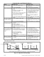
Страница 18: ...on reading is not what is expected 1 Stem position sensor mounting is off 180 degrees 2 Stroke not calibrated 3 Tight shutoff M P C is active 4 Custom characterization or soft stops active Position is driven fully open or closed and will not respond to com mand 1 Stroke not calibrated 2 Inner loop hall sensor not connected 3 Wrong air action entered in software 4 Actuator tubing backward 5 Electro...

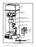
Страница 19: ... Exploded View Cover Item No 1 Electronic Control Boards Item No 2 E P Piezo Driver Pneumatic Amplifier Relay Unit Item No 3 Feedback Potentiometer Assembly Item No 4 Feedback Gear Shaft Item No 5 Limit Switch Assembly Item No 6 Base Housing Item No 7 Follower Item No 8 Follower arm ...

Страница 20: ...tinually improving and upgrading its product design the specifications dimensions and information contained herein are subject to change without notice Should any question arise concerning these provisions the purchaser user should contact Flowserve Corporation at any of its worldwide operations or offices For more information contact For more information about Flowserve and its products contact w...

Отзывы: