51-16
Flowserve Corporation, Valtek Control Products, Tel. USA 801 489 8611
HART 275 HANDHELD COMMUNICATOR
AND SOFTTOOLS CONFIGURATION AND
DIAGNOSTIC SOFTWARE
The Logix 520 supports and is supported by the HART
275 Handheld Communicator. The DD and the manu-
als listed below can be obtained from the HART
Communication Foundation or from your Flowserve rep-
resentative. For more information please see the fol-
lowing guides:
•
Product Manual for the HART Communicator
•
Logix 520 Digital Positioner with HART 275
Communicator User Guide
Flowserve corporation has written custom configura-
tion and diagnostic software for the Logix 500 series
called SoftTools™. This software and the
SoftTools
Quick Start Guide are available from a Flowserve rep-
resentative.
LIMIT SWITCH UNIT (Optional)
CAUTION: The installation of explosion proof elec-
trical equipment must comply with the procedures
contained in the certificates of conformance. Coun-
try specific regulations may apply. Electrical safety
is determined only by the power supply device
(Positioner operation with limited voltage only).
General
The Logix 500 digital positioner can be equipped with
an additional limit switch unit, designed as a two-wire
sensor in accordance with NAMUR. The low voltage
and current characteristics of these sensors allows
operation in hazardous areas.
Model Selection
To select the suitable Logix 500 version see product
information.
Principle of operation
The stroke of the diaphragm actuator or the rotary angle
of the rotary valve actuator is picked up by a stroke
lever or by a coupling at the actuator connection. The
lever/coupling moves the vane into the slot of the limit
switches LS1 or LS2 via shaft. The sensors are de-
signed as a proximity vane type switch. The switching
function is triggered if a ferromagnetic object (vane) is
inserted between the coils. The switching point can be
set by adjustment of the vane.
Installation
The limit switch unit is delivered already fitted to the
positioner and can not be retrofitted.
Start-up
After the Logix 500 digital positioner start-up in accor-
dance with the application is complete, the limit switch
unit can be adjusted and operation can be effected.
For adjustment remove the positioner cover. Figure 14
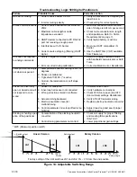
shows the maximum switching range of the limit
switches LS1 and LS2.
The switching points of the limit switches can be set by
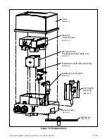
an adjustment of the vane as follows (Figure 13):
1. Loosen the knurled screw (Figure 13) at the stroke
lever axis (1/2 to 1 rotations).
2. Move the positioner to the first switching position.
3. Set the switching point of the limit switch LS2 by
adjusting the vane of the lower switch. For adjust-
ment turn the corresponded slotted screw clock-
wise or counterclockwise.
4. Move the positioner to second switching position.
5. Set the switching point of the limit switch LS1 by
adjusting the vane of the upper switch. For adjust-
ment turn the corresponded slotted screw clock-
wise or counterclockwise.
6. Tighten the knurled screw.
7. Check the two switching points and repeat the
adjustment steps 1 to 6, if necessary.
Figure 12: Principle of Operation
Linear Version
Rotary Version
Rotary Valve Actuator
Limit Switch Unit
Limit Switch Unit
+
-
+
-
Diaphragm Actuator
Stroke
Lever
Butterfly Damper


