background image

11

TOGGLE & CONTROL CENTER

TOGGLE & CONTROL CENTER

TOGGLE & CONTROL FEATURES 

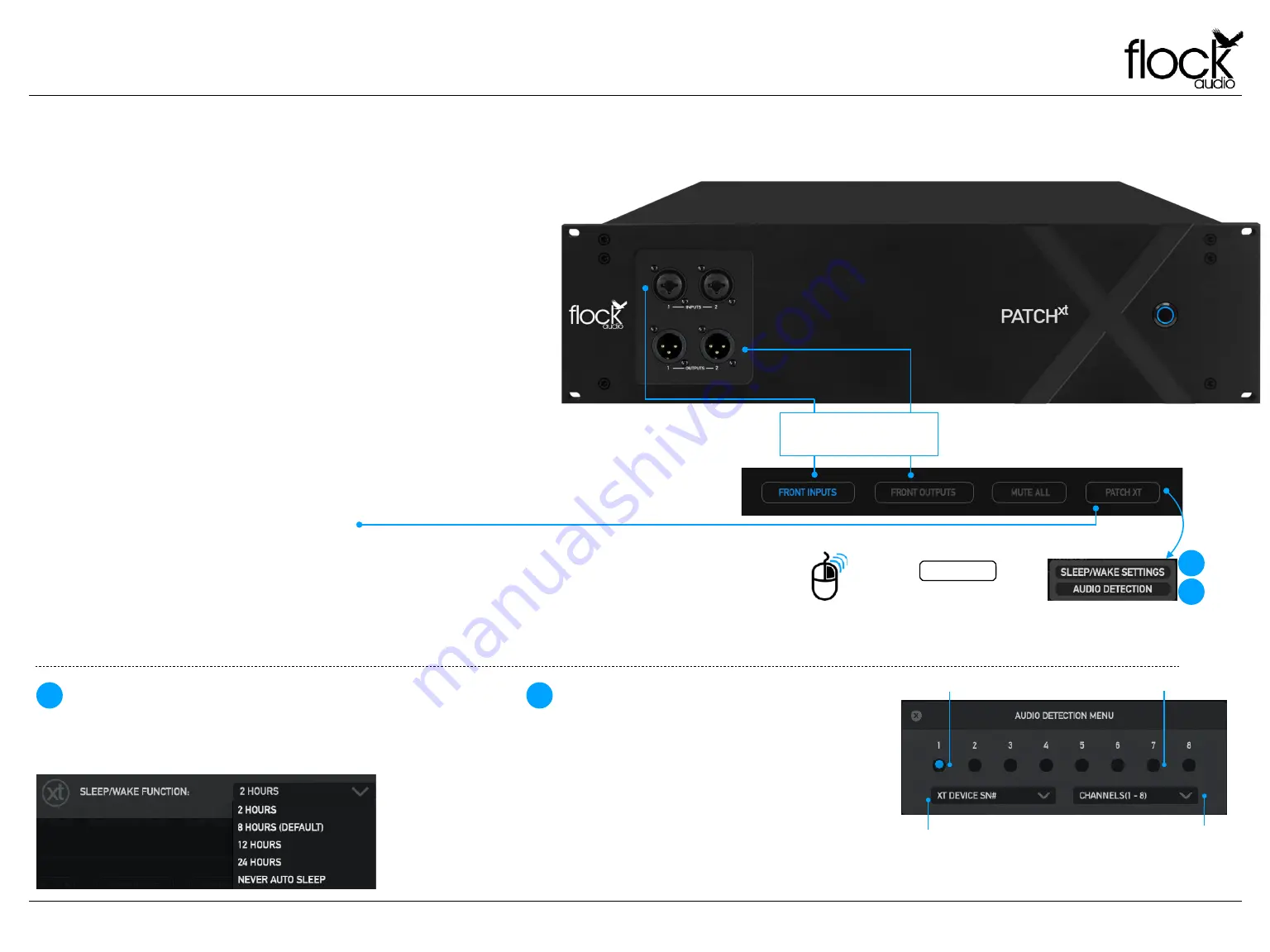
The  PATCH  XT  Hardware  will  allow  a  user  to  redirect  Inputs    and/or 

Outputs 1-2 from the rear side of the system to the front panel for easy 

access and integration of outside analog audio equipment.  

This function can be engaged by clicking the “Front Inputs” or “Front 

Outputs” toggle buttons located in the bottom section of the software 

application.  A  prompt  notification  will  alert  the  user  that  the 

corresponding Inputs &/or Outputs will no longer be actively functioning 

on the rear side of the PATCH XT Hardware unit when the Front Inputs 

or Outputs are activated in the application. 

Note: Inputs 1-2, when redirected to the front panel Input Connectors, 

will have the ability to have 48V Phantom Power supplied to them when 

using the PATCH APP software controller.

FRONT PANEL INPUTS & OUTPUTS

Toggle Front Inputs & Outputs 

1-2 Rerouted from Rear Panel 

Connections to Front Panel   

PATCH

XT

 MANUAL

PATCH XT BUTTON & OPTIONS

When a PATCH XT unit is connected to the Host CPU, a PATCH XT Button 

Icon will appear/display. The main purpose of this button is to allow the User 

to remotely “Sleep/Wake” their PATCH XT Hardware unit. The User can also 

Right  Click  this  Button  which  will  display  additional  PATCH  XT  specific 

options including: "Sleep/Wake Settings" and "Audio Detection”.

SLEEP/WAKE SETTINGS

This  PATCH  XT  specific  feature  allows  the  user  choose  a  time-out 

interval  after  which  PATCH  XT  will  automatically  go  to  sleep  if  it 

doesn't receive any new commands from the PATCH APP Software.

AUDIO DETECTION

This  feature  launches  a  menu  where  the  user  can 

choose  a  set  of  any  eight  corresponding  input 

channels  (DB25/D-SUB)  to  monitor  and  confirm 

incoming signals. The channel indicators will illuminate 

when  an  audio  signal  is  detected  on  the  specified 

channels.

Audio Detected

No Audio Detected

Right Click  PATCH XT  Button 

to access additional options

ADDITIONAL PATCH XT OPTIONS 

(RIGHT CLICK OPTIONS) 

1

2

1

2

Select  Connected  PATCH 

XT Unit Hardware Serial #

Choose  any  8  Channels 

b a s e d  o n  D 2 5 / D S U B 

Connection to confirm Audio 

Input Incoming Channels

Содержание Patch XT

Страница 1: ...USER MANUAL V 1 0 0 ...

Страница 2: ...ns 7 Rear Panel Identifications 8 Rear Panel Cable Connections 9 Hardware Chassis Measurements 10 Toggle Control Center 11 Routing Examples Pt 1 12 Routing Examples Pt 2 13 Routing Examples Pt 3 14 Front Panel LED Indicator 15 Install New Firmware 16 Introducing the XTH Cable Hanger 17 Assembling the XTH Cable Hanger 18 Troubleshooting 19 Software System Requirements 20 User Notices Warranty 21 En...

Страница 3: ...it After 2 years of strenuous work and constant focus Flock Audio the company I started created the worlds fi rst and most advanced digitally controlled analog audio routing system with features never before possible in conventional analog audio routing I m honoured to have so many customers believe in what Flock Audio stands for Innovations above Expectations We have an incredible team of profess...

Страница 4: ... fl ows from top to bottom Signal fl ows are divided up into single vertical columns allowing users to drag drop available analog audio equipment connected to the PATCH XT s Hardware component This analog audio equipment is cataloged in the Hardware Index located to the left side of the PATCH APP The PATCH XT Hardware component is a 3U rack mountable unit that acts as the centrepiece hub of an aud...

Страница 5: ...Cable 110V 220V with your PATCH XT System The Chassis is designed to work with the earth ground inside the box for both a safe quiet audio operation Never remove or use a IEC cable accessory without the grounding pin 5 Use Properly Grounded IEC Power Cables Although no damage or immediate danger will occur if 48V Phantom Power is engaged on a Preamp connected to the Input of the PATCH XT System it...

Страница 6: ...HATS IN THE BOX WHAT S IN THE BOX WHAT S INCLUDED IN THE BOX USB A TO USB B 6FT LOCKING 6 STEP QUICKSTART GUIDE IEC POWER CABLE 110V or 220V PATCHXT 3U HARDWARE HARDWARE INDEX SETUP QR CODE PATCHXT MANUAL ...

Страница 7: ...mbo Jacks Activated using Software Front Outputs 1 2 Neutrik XLR Male Jacks Activated using Software Multi Purpose LED Indicator Blue LED Indicator Learn more on Page 33 Sleep Wake Button Toggle On Off Sleep Wake Mode FRONT PANEL FRONT INDENTIFICATIONS PATCHXT MANUAL ...

Страница 8: ... per Connector Tascam 25 Pinout Wiring Standard Inputs Outputs 1 2 Channels 1 2 can be routed to the Front Panel Inputs Outputs using the PATCH APP Software REAR PANEL INDENTIFICATIONS IMPORTANT Always ensure that the Power Connector is inserted securely into the Power Input of the PATCH XT System Hardware NOTE PATCH XT IS DESIGNED WITH A FIXED PROFESSIONAL LINE LEVEL OF 4 TO WORK IN ACCORDANCE WI...

Страница 9: ...EM OR OTHER EXTERNAL HARDWARE THAT IS C O N N E C T E D T H AT Y O U M A K E T H E P R O P E R CONNECTIONS ACCORDINGLY TO LEARN MORE OF ABOUT PROPERLY CONNECTING EXTERNAL HARDWARE TO THE PATCH SYSTEM SEE THE BOTTOM OF THIS PAGE INPUTS OUTPUTS NOTICE CONNECTING PATCH XT TO EXTERNAL HARDWARE EXAMPLE NOTE ALL EXTERNAL HARDWARE MUST BE CONNECTED IN THIS METHOD SHOWN TO THE LEFT SIDE OF THIS DESCRIPTIO...

Страница 10: ...m 12 75 in 133 4 mm 5 25 in 482 6 mm 19 in 425 mm 16 75 in HARDWARE CHASSIS MEASUREMENTS FRONT VIEW REAR VIEW CHASSIS DIMENSIONS 25 lbs 11 3 kg Weight 482 6 mm 19 in 133 4 mm 5 25 in 425 mm 16 75 in 323 9 mm 12 75 in PATCHXT MANUAL ...

Страница 11: ... PATCH XT BUTTON OPTIONS When a PATCH XT unit is connected to the Host CPU a PATCH XT Button Icon will appear display The main purpose of this button is to allow the User to remotely Sleep Wake their PATCH XT Hardware unit The User can also Right Click this Button which will display additional PATCH XT speci fi c options including Sleep Wake Settings and Audio Detection SLEEP WAKE SETTINGS This PA...

Страница 12: ...rd audio engineering practices should be exercised such as the understanding that mixing signal levels may or may not exhibit audio level or electronic noise floor artifacts If undesired results are experienced when connecting microphones directly to the PATCH Series it is recommended to have a dB booster or transparent preamp between the microphone and PATCH Model connection I E Mic Pre dB Booste...

Страница 13: ...ering practices should be exercised such as the understanding that mixing signal levels may or may not exhibit audio level or electronic noise floor artifacts If undesired results are experienced when connecting microphones directly to the PATCH Series it is recommended to have a dB booster or transparent preamp between the microphone and PATCH Model connection I E Mic Pre dB Booster PATCH to achi...

Страница 14: ... EXAMPLES Interface Input Saturation Harmonics EQ Compressor Interface Output Interface Input EQ Compressor Interface Output Mixing Mastering Routing Example Saturation Harmonics PATCHAPP MANUAL HARDWARE SOFTWARE ROUTING EXAMPLE ...

Страница 15: ...LED INDICATOR PATCHXT MANUAL Solid Illuminated Powered On Active Connection to Host CPU Slow Fade In Out Powered On Active Connection But In Sleep Mode Flash On O ff Repeatedly Fast System Error Fault Overheated etc No Illumination System Powered O f ...

Страница 16: ... at www fl ockaudio com Step 2 Follow the process and prompts on the fi rmware installer application on your computer to complete the fi rmware installation Once complete restart your PATCH XT System and the PATCH APP to complete the installation process Note If there are any issues installing the new firmware please contact Flock Audio Support NOTE THIS PROCESS DOES NOT REFLECT SOFTWARE UPDATES F...

Страница 17: ... exclusively for the PATCHXT Model The XTH Cable Hanger ships as a 4 piece kit and assembles in minutes to mount securely to the rear panel of the PATCHXT chassis with 4 Included Fastener s Hex Key The XTH Cable Hanger creates a strain relief bene fi t on the PATCHXT Chassis when all 24 DB 25 D SUB Cables are connected to the rear panel of the system DB 25 D SUB Cables can vary in weight from manu...

Страница 18: ...ASSEMBLING THE PATCH XT CABLE HANGER 18 ASSEMBLING THE XTH CABLE HANGER PATCHXT MANUAL ...

Страница 19: ...of your System change speeds depending on the amount of cooling required Fan Controls can be customized by going Settings User Preferences Hardware Fan Controls The fans are mounted deep inside the chassis not near any exterior facing panel Never block or restrict air fl ow to the PATCH XT Hardware Unit Always ensure this fan is not blocked by cables or anything else restrictive Slight popping or ...

Страница 20: ...Hz operating frequency Memory RAM 4GB Minimum 8GB or more Recommended Internet Connection Internet Connection is required for download and updates OSX 10 12 Sierra or Newer Disk Space Minimum 512 MB available disk space USB 1x USB 2 0 3 0 Port Per PATCH Series System Required USB bandwidth 5 10 Memory RAM 4GB Minimum 8GB or more recommended CPU Intel Core 2 Duo Minimum Intel Core i3 or higher Reco...

Страница 21: ...udio PATCH XT System and will void any active warranty immediately The PATCH XT System does not contain any user replaceable or removable parts Any User Maintenance or Repairs are required to be performed by a Certi fi ed Flock Audio Support repair service technician These Certi fi ed Support Technicians can be located by visiting Flock Audio Support www fl ockaudio com support USER MAINTENANCE Wh...

Страница 22: ... 2022 Flock Audio Inc All Rights Reserved www flockaudio com PATENT PENDING ...

Отзывы: