background image

FAD-40 Technical Manual, Rev.2.1.0;   February 2022 

Page 43 of 55 

8.3.  Ethernet Interfacing 

FAD-40EN instruments have two interface connectors on the front of the instrument: Ethernet and RS-232C. 
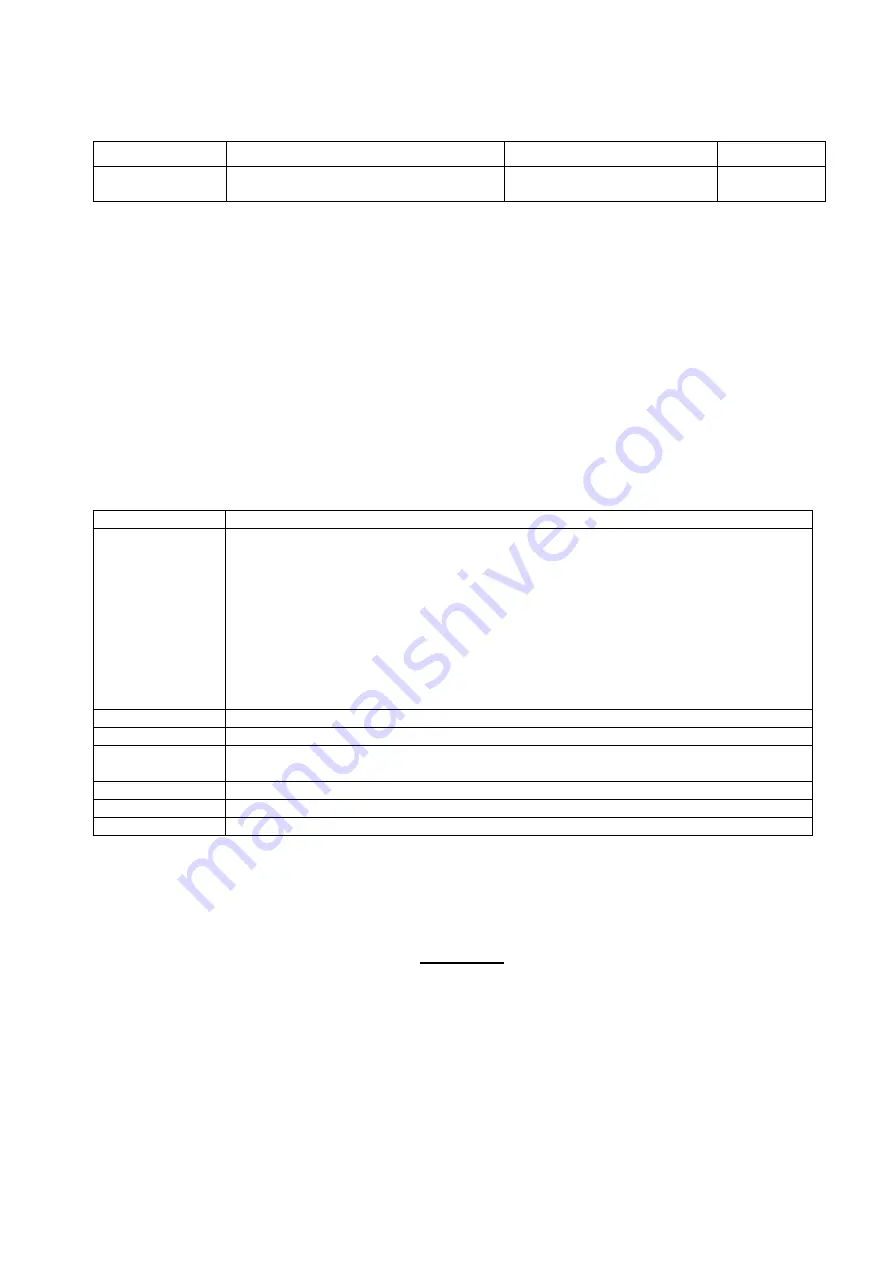
The table below describes the data formats for interfacing the peripherals and their application: 


Data Format 

Description 

Application 

Hardware 

Modbus TCP/IP 

Ethernet interfacing. 
Refer to chapter 6.7 

Interfacing with PLC 

Ethernet 

Table 9.2 

– Data output interfacing 

ATTENTION:

 Please disable the interface you will not use to increase the performance of the instrument. 


8.4.  Setup and Calibration 

FAD-40EN instruments are set up and calibrated by xFace. The A/D Converter settings are very important for a 
good weighing performance. Please refer to chapter 5.3. 
 

8.5.  Ethernet Setup 

The Ethernet setup is done by xFace software as described in this chapter. Select the Gateway tab after 
connecting xFace to the instrument. You will see the Ethernet parameters in this tab. 

Ethernet Setup 

There are 11 setup parameters for the Ethernet network as described below: 


Host Name 

Device name of the instrument. Default is ‘ ’. 

Data Format 

This parameter defines the data format for the Ethernet port.  
The available settings are: 


Disable 

:  No data will be transmitted. 

Select disable if this port is not used. 

Modbus-TCP/IP 

:  Modbus TCP/IP communication.  

Refer to 

chapter 6.7

 for details. 


IP Address 

Define IP address manually. Default is ‘192.168.16.250’ 

Local Port 

Ethernet connection port of the 

instrument. Default is ‘10001. 

Gateway 

Network point that acts as an entrance to another networks. Default is 
‘192.168.16.254’. 

Subnet Mask 

Defines IP addresses which can be used in network. Default is ‘255.255.255.0’. 

Primary DNS 

Define primary DNS 

manually. Default is ‘208.67.222.222’. 

Secondary DNS 

Define secondary DNS manually. Default is ‘208.67.220.220’. 


8.6.  Modbus Data Structure 

If the instrument is set up for Modbus TCP/IP, it can be used as a Modbus TCP/IP slave on an Ethernet 
communication network. The function codes ‘0x03’ and ‘0x10’ are supported. 

For the Modbus Data Structure please refer to chapter 6.6. 


Содержание FAD-40 Series

Страница 1: ...FAD 40 A D Converter Technical Manual Flintec www flintec com...

Страница 2: ...terface Setup 19 4 7 Bus Addressing via Setup Switch 20 4 8 Back up Settings and Calibration Data 20 5 FAD 40 FAD 40MB WITH RS 485 INTERFACE 21 5 1 Front View of FAD 40 MB 21 5 2 Electrical Connection...

Страница 3: ...lting from the use of the information contained herein The information herein is believed to be both accurate and reliable FLINTEC however would be obliged to be informed if any errors occur FLINTEC c...

Страница 4: ...ARE WHEN MAKING CHECKS TESTS AND ADJUSTMENTS THAT MUST BE MADE WITH POWER ON FAILING TO OBSERVE THESE PRECAUTIONS CAN RESULT IN BODILY HARM WARNING FOR CONTINUED PROTECTION AGAINST SHOCK HAZARD CONNEC...

Страница 5: ...cial feature the instruments can switch between unipolar and bipolar input range without affecting the external resolution Digital I O ports give further possibilities to extend the bus system with I...

Страница 6: ...es Yes Yes Yes Up to 6 load cells 350 or 18 load cells 1100 Yes Yes Yes Yes Yes Yes Electronic calibration eCal without test weights Yes Yes Yes Yes Yes Yes Zero and Span calibrations over bus interfa...

Страница 7: ...85 interface Type FAD 40 Communication Serial interface RS485 1200 to 57600 baud 8N1 7E1 7O1 bus capability up to 31 units Communication mode Requested Dimensions weight 99 x 22 5 x 114 5 mm L x W x H...

Страница 8: ...Side view View A FAD 40 FAD 40MB View B FAD 40PB FAD 40PN FAD 40EN FAD 40CO Figure 3 2 Dimensions 2 4 Accessories 2 4 1 Accessories supplied with the instrument The following accessories are supplied...

Страница 9: ...nd of equipment Install parallel reverse diodes to the DC inductive loads like relays solenoids etc to minimize voltage peaks on the DC power lines 3 1 2 Cabling All cables coming to the control cabin...

Страница 10: ...should be made carefully before energizing the instrument Load cell connection details are shown below in figure 4 2 In 4 wire installations the sense and excitation pins with the same polarity shoul...

Страница 11: ...2 4 Serial Interface RS232 You can use the serial interface RS232 with the xFace software for configuration and adjustment FAD 40EN FAD 40PB FAD 40PN and FAD 40CO Front view 24V 0V TX RX GND Shield Fi...

Страница 12: ...of untrained person may cause some unwanted damages or injuries Before energizing the instrument please make the required mechanical and electrical installations After power on you have to setup your...

Страница 13: ...ll inform you about the success of the software installation Click the OK button After closing the Setup Wizard you can start to use the xFace software Typ FAD 30 Typ FAD 40 Select one of the FAD 40 m...

Страница 14: ...D 40 Setup Parameters For entering the parameter values enter the setup tab adjust the parameter settings and then write this data to the A D Converter After changing parameter settings the instrument...

Страница 15: ...tting 20 40 Auto Zero Tracking AZT automatically re adjusts the scale to zero for compensating defined small deviations around the center of zero AZT only works within the defined zeroing range and st...

Страница 16: ...The data length and parity can be selected as 8 None 1 default 7 Odd 1 or 7 Even 1 Address of A D Converter The address range is 01 default to 31 If you enter 0 the instrument will operate without add...

Страница 17: ...cale Build The scale capacity the increment and the unit have to be introduced to the FAD 40 instrument before you can perform a calibration in Weighing or Force mode Capacity To select a new value fo...

Страница 18: ...oaded test weight value then click the OK button The scale must be stable in this period Approximately 5 seconds later the new calibration settings are saved automatically Please refer to the chapter...

Страница 19: ...ersion For convenience keys for Taring Zeroing and Clear are located in this tab Figure 5 7 A D Status 4 5 Setup of Digital I O FAD 40 instruments have 3 digital I O channels I O1 is always an output...

Страница 20: ...s for the selected output function Host output needs no setpoint value Click Write to Converter to save the changes Setup of Digital Input Function I O2 and I O3 can be set up with the input functions...

Страница 21: ...ged by pressing the setup switch sequentially To save and exit press the setup switch for 5 seconds To return to normal operation without saving wait 15 seconds without pressing the switch Err Address...

Страница 22: ...12 When the error LED is ON the other two LED indicate the error type Refer to chapter 11 for details Load cell connection power supply and serial interface terminals are located at the front of the...

Страница 23: ...s RTU Interfacing FAD 40 and FAD 40MB instruments have one serial interface connector on the front of the instrument RS 485 The table below describes the data format for interfacing the peripherals an...

Страница 24: ...onse format with weight force or count data A general description of the response is the following ADR COMMAND STATUS SIGN WEIGHT FORCE COUNT CHK CR LF Response format without weight force or count da...

Страница 25: ...ale is in gross mode ADR C X Clear command is unavailable in count mode Comments The response status is always Ack in weighing or force mode and always X in count mode D Read Count value immediately C...

Страница 26: ...H SP VALUE data is 8 byte ASCII char with dot and non significant zeros on the left S Read Status Command ADR S Response ADR S STATUS 1 STATUS 2 STATUS 3 Example Command 01S Response 01SSGI Stable Gro...

Страница 27: ...ble and 123 41 or 01XE Error Comments The response includes the weight data with the increment divided by 10 Z Zero Command ADR Z Response ADR Z A Zeroed ADR Z N Zeroing could not be operated ADR Z X...

Страница 28: ...eight 40006 R 2 Gross weight 40008 R 1 Status Motion Net mode Data ok image of register 40003 40009 R W 1 Control 0 None 1 Zero 2 Tare 3 Clear 40010 R W 1 Calibration 0 None 188 Adjust Zero Calibratio...

Страница 29: ...output function 0000001 Standard setpoint 0000010 Setpoint without hyster 0000011 Window 0000100 Host output D7 0 Active Low I O1 polarity 1 Active High D8 D14 0000000 Disable I O2 output function 00...

Страница 30: ...g 01 10 00 08 00 01 02 00 02 26 D9 Request tare data 01 03 00 03 00 02 34 0B Answer of requested tare 01 03 04 00 00 27 10 E0 0F Tare is 10000 Weight Mode Selection 01 10 00 0D 00 01 02 00 04 A6 8E Co...

Страница 31: ...6 and for diagnostics Refer to chapter 12 When the error LED is ON the other two LED indicate the error type Refer to chapter 11 for details Load cell connection Profibus connection power supply and s...

Страница 32: ...Connector DB9F Pin Signal Description 1 2 3 B Line Positive RxD TxD RS 485 level 4 RTS Request to send 5 GND Bus Ground isolated 6 5V Bus output 5V termination power isolated 7 8 A Line Negative RxD...

Страница 33: ...put interfacing Attention Please disable the interface you will not use to increase the performance of the instrument 6 4 Setup and Calibration FAD 40PB instruments are set up and calibrated by xFace...

Страница 34: ...o PLC Input Dword D31 D30 D29 D28 D27 D26 D25 D24 D23 D22 D21 D20 D19 D18 D17 D16 D15 D14 D13 D12 D11 D10 D9 D8 D7 D6 D5 D4 D3 D2 D1 D0 1st Dword Reserved 2nd Dword W31 MSB W30 W29 W28 W27 W26 W25 W24...

Страница 35: ...ystem ready for calibration 0000 0011 Zero calibration in process 0000 0100 Span calibration in process 0000 1001 Error Calibration error FAD 40Px Output to PLC Input 3rd Dword Bit no 3rd Dword Descri...

Страница 36: ...40Px Input 3rd Dword I O Configuration Bit no 2nd Dword description D0 D6 I O1 output function 0000000 Disable 0000001 Standard setpoint 0000010 Setpoint without hysteresis 0000011 Window Checkweigher...

Страница 37: ...d Dword with one of these 0 5 mV 1 10 mV 2 15 mV 3 18 mV 01010 Digital filter First load 2nd Dword with selected value then apply this command with New CMD Load 2nd Dword with one of these 0 Fast 5 Me...

Страница 38: ...ror LED is ON the other two LED indicate the error type Refer to chapter 11 for details Load cell connection Profinet connection power supply and serial interface terminals are located at the front of...

Страница 39: ...f No Link No link no communication present Green Link Ethernet link established no communication present Green flickering Activity Ethernet link established communication present NS Network Status LED...

Страница 40: ...et setup is done by xFace software as described in this chapter Select the Gateway tab after connecting xFace to the instrument You will see the Profinet parameters in this tab There are 7 setup param...

Страница 41: ...K will be displayed as shown below 7 6 Profibus and Profinet Data Structure for FAD 40Px only To install the FAD 40PN into the PLC Hardware Configuration use the GSDML file memory parts to create exac...

Страница 42: ...error type Refer to chapter 11 for details Load cell connection Ethernet power supply and serial interface terminals are located at the front of the DIN rail mount instrument See figure 9 1 Status LED...

Страница 43: ...g will be a direct connection as shown below Figure 9 2 HUB connection The PC connection cabling will be done via cross cable as shown below Figure 9 3 Direct PC connection with cross cable FAD 40EN i...

Страница 44: ...et parameters in this tab Ethernet Setup There are 11 setup parameters for the Ethernet network as described below Host Name Device name of the instrument Default is Data Format This parameter defines...

Страница 45: ...stics Refer to chapter 12 When the error LED is ON the other two LED indicate the error type refer to chapter 11 for details Load cell connection CANopen connection power supply and serial interface t...

Страница 46: ...flash Warning limit reached Bus error counter reached or exceeded its warning limit Red flickering LSS LSS services in progress Red double flash Error count event A guard NMT slave or master or heartb...

Страница 47: ...cing the peripherals and their application Data Format Description Application Hardware CANopen CANopen interfacing Refer to chapter 5 13 Interfacing with PLC CANopen Table 11 3 Data output interfacin...

Страница 48: ...W2 contains the weight value respective the calibration information according to the read command response Refer to PLC Output to FAD 30CO Input T_DW3 Calibration Status Bit no TxPDO 2 T_DW2 descripti...

Страница 49: ...nse 00000 Indicated weight 00001 Gross weight 00010 Tare weight 00011 Indicated weight floating point type 00100 Gross weight floating point type 00101 Tare weight floating point type 10000 Calibratio...

Страница 50: ...000 Disable 0000001 Standard setpoint 0000010 Setpoint without hyster 0000011 Window 0000100 Host output I O2 input functions 0000101 Zeroing 0000110 Taring 0000111 Clearing tare 0001000 Host input D1...

Страница 51: ...one of these 0 5 mV 1 10 mV 2 15 mV 3 18 mV 01010 Digital filter First load 2nd Dword with selected value then apply this command with New CMD Load R_DW2 with one of these 0 Fast 5 Medium 7 Default 9...

Страница 52: ...r Re energize the instrument Instrument could be defective Overload Check the load Load cell or instrument could be defective Weight is too low ADC out Check the load Check the calibration Load cell o...

Страница 53: ...232C RxD not for FAD 40 and FAD 40MB LED gets off 0 3 s after receiving any data Press the setup switch to go to the next test step RS 232C TxD not for FAD 40 and FAD 40MB A to Z characters are sent...

Страница 54: ...Interface 22 FAD 40CO with CANopen Interface 45 FAD 40EN with Ethernet Interface 42 FAD 40PB with Profibus 31 FAD 40PN with ProfiNet 38 features 6 Housing 8 HUB connection 43 I O Polarity 20 Increased...

Страница 55: ...FAD 40 Technical Manual Rev 2 1 0 February 2022 Page 54 of 55 http www flintec com...

Отзывы: