


Maintenance
8.4 Removing coupling parts 1 (1), 2 (2), 3 (3) or the rubber disk element 5 (5) of type EST
52
Edition 09/2022
M3302-01en
• Suitable connections and pipes.
• Suitable pulling fixture.
Or:
Retaining plate with retaining screws or threaded spindles with nuts. Material of the
screws and spindles must have at least strength class 10.9; material of the nuts depend-
ing on the material of the screws or spindles.
• Hydraulic cylinder with oil pump. Note displacement and pressure of the hydraulic cylin-
der. Refer to the dimension drawing for the required axial force.
Procedure
1. Secure the coupling parts to prevent them from falling.
2. Move the coupled machines apart.
3. Loosen the bolt connection (25) and dismantle the rubber disk element 5 (5) and/or 6
(6).
4. For types ESNW and ESDW, you can remove the entire assembly unit consisting of
coupling part 1 (1) with attached flange (101) and coupling part 3 (3). If you would like to
remove the flange (101) and the coupling part 3 (3), remove the bolt connection (125
and 31).
5. Use a suitable pulling fixture.
6. Secure the coupling part 1 (1) or 2 (2) and the pulling fixture in position to prevent them
from falling.
7. Remove the screw plugs (101) or (201) from the oil channels.
8. Deaerate an oil pump and connect it to the oil channel in the centre.
9. Pressurise the oil pump to the pressure specified in the dimension drawing until oil starts
to escape from the adjacent connections or the front faces. Keep the pressure constant.
10.Deaerate the next oil pump and connect it to the adjacent oil channel.
11.Repeat steps 9 and 10 on the remaining oil channels.
12.If so much oil escapes when pressure is applied that the pump cannot maintain the pres-
sure, use a higher-viscosity oil.
13.Pressurise the hydraulic cylinder if oil escapes from both front faces as a closed oil ring.
Make sure that the coupling part 1 (1) or 2 (2) is pulled immediately off the shaft in a
swift, smooth movement.
NOTICE
Removal in several strokes
If several strokes of the hydraulic cylinder are required to remove the part, make sure that
the shaft end is positioned between two oil channels at the end of the stroke.
14.Dismantle the oil pumps and the pulling fixture from the coupling part 1 (1) or 2 (2) .
15.Check the hub bore and the shaft for damage and protect them against corrosion.
16.Replace damaged parts.
When reinstalling the coupling parts please observe the information in chapters Assembling
(Page 27) and Commissioning (Page 39).
Содержание ELPEX-S
Страница 6: ...Table of contents 6 Edition 09 2022 M3302 01en ...
Страница 8: ...List of tables 8 Edition 09 2022 M3302 01en ...
Страница 10: ...List of figures 10 Edition 09 2022 M3302 01en ...
Страница 14: ...Introduction 1 4 Copyright 14 Edition 09 2022 M3302 01en ...
Страница 22: ...Description 22 Edition 09 2022 M3302 01en Structure ...
Страница 38: ...Assembling 5 3 Aligning the coupling 38 Edition 09 2022 M3302 01en ...
Страница 40: ...Commissioning 40 Edition 09 2022 M3302 01en ...
Страница 46: ...Operation 7 2 Fault causes and correction 46 Edition 09 2022 M3302 01en ...
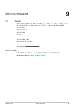
Страница 56: ...Service and support 9 1 Contact 56 Edition 09 2022 M3302 01en ...
Страница 58: ...Disposal 58 Edition 09 2022 M3302 01en ...