Flash Technology
Revision A - 2/13/2020
42
SECTION 3:
INFORMATION DISPLAY
NAVIGATING THE INFOR MATION DISPLAY
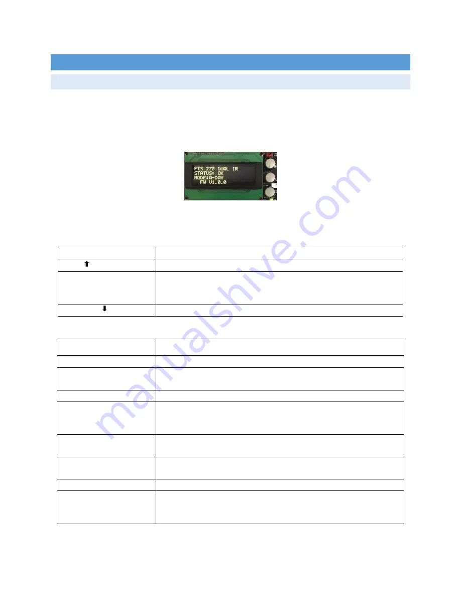
Three pushbuttons to the right of the information display provide access to navigate the system menus, configure
the system and review diagnostic information.
Table 3-1 describes the function of each button. The top level menu is described in Table 3-2. Each menu option
is discussed in the headings following Table 3-2.
Figure 3-1: Information Display
Table 3-1: Controller Display Buttons
1
Button
Function
S1 UP
Navigates UP through the active menu options.
S2 ENTER
Confirms your selection or Advances to the NEXT option.
Press and hold for
1.5 seconds then release to return to the previous menu. Press and hold for
longer than 5 seconds to return to the main menu.
S3 DOWN
Navigates DOWN through the active menu options.
Table 3-2: Top Level Menu Options
1
Menu Option
Description
SITE TOWER CONFIG
Selects the overall system configuration.
MONITORING CONFIG
Selects the type of monitoring equipment that will be used to monitor the
system.
MONITORING STATUS
Provides status of the built in monitoring system.
LOCAL DIAGNOSTICS
Displays the firmware revision and multiple analog values for the controller,
beacon and markers. This menu is especially helpful when troubleshooting
the system.
LIGHTING INSPECTION
Allows the user to perform a lighting inspection. Automatic and Manual
modes are available.
MODE OVERRIDE
Allows the system to be manually placed in any capable mode for a user
definable period of up to 24 hours.
FACTORY TEST
Factory use only.
SYSTEM SETTINGS
Allows the user to reboot the system without physically interrupting input
power or to restore configuration settings to factory default values.
Also
allows setting the real time clock’s date/time + timezone
1. Menu options and features are based on firmware version 10/25/2019 (V ?.0.1).


