background image


321144 


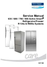
Service Manual 

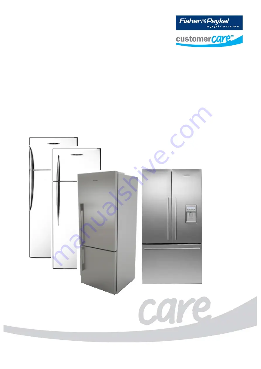
635 / 680 / 790 / 900 Active Smart

®


Refrigerator/Freezer 

R134a & R600a Systems 


Содержание 635 Active Smart

Страница 1: ...321144 Service Manual 635 680 790 900 Active Smart Refrigerator Freezer R134a R600a Systems...

Страница 2: ...321144 2...

Страница 3: ...0 Ubi Avenue 4 Sunlight Building 02 00 Singapore 408825 Telephone 65 65470100 Facsimile 65 65470123 Fisher Paykel Appliances 5800 Skylab Road Huntington Beach CA 92647 Telephone 888 936 7872 Fisher Pa...

Страница 4: ...2 1 Ice Water Models 20 4 2 2 Non Ice Water Models 21 4 3 Defrost Cycle 22 4 3 1 R134a System 22 4 3 2 R600a System 23 4 4 The Refrigeration Circuit 24 4 5 Evaporator 24 4 6 Condensate Disposal 25 4...

Страница 5: ...de 50 7 3 7 Dispenser Lock 50 7 3 8 Key Lock 50 7 3 9 Filter Replacement Alert 50 7 4 Key Presses 51 7 5 Temperature Settings 51 8 ICEMAKER 52 8 1 Ice Production 52 8 2 Information About The Icemaker...

Страница 6: ...val E402B and E372B Models 90 12 6 FC Bin Removal 900 Models 90 12 7 FC Drawer Removal 900 Models 91 12 7 1 Refitting Of The FC Drawer 91 12 8 PC Fan Motor T Models 92 12 9 PC Fan Motor B Models 92 12...

Страница 7: ...pressor 117 14 6 900 Models Wiring Diagram Reciprocating Compressor 118 14 7 900 Models Power Module Wiring Connections VC Compressor 119 14 8 900 Models Wiring Diagram VC Compressor 120 14 9 B Model...

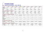
Страница 8: ...play Module P No 881218P P No 881218P P No 881218P P No 881218P P No 881218P P No 881218P P No 881218P P No 881218P P No 881218P Display Module Ice Water N A N A N A P No 821074P N A N A N A N A N A P...

Страница 9: ...res 21 7 c ft ELECTRONICS 230 240V FOR SPARE PARTS Display Module P No 814321P P No 814321P P No 814321P N A Display Module Ice Water P No 821074P N A P No 821074P P No 821074P Power Control Module No...

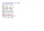
Страница 10: ...s 226 litres Freezer FC 123 litres 97 litres Humidity Dr N A 88 litres TOTAL 403 litres 411 litres ELECTRONICS 100 110V FOR SPARE PARTS Display Module P No 881218P P No 881218P Display Module Ice Wate...

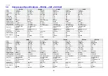
Страница 11: ...18GCF 209083 MM3 18GCF 209083 5TM22NFBYY 207224 5TM205NFBYY 207222 Gas charge 120 Grams 130 Grams 120 Grams 140 Grams 150 Grams 150 Grams 130 Grams 140 Grams 130 Grams Start Capacitor N A N A N A N A...

Страница 12: ...814809P 4 F 814809P Inverter N A N A 207309 N A N A N A E442B E521T E522B RF540A RF610A Make Embraco Embraco Embraco Embraco Embraco Embraco Embraco Model EGX80CLC VEMC9C EGX80CLC EGX90CLC VEMB11C VEM...

Страница 13: ...al BTU 695 695 330 965 Run current 1 04 amps 1 04 amps 0 8 2 23 amps Refrigerant type R134a R134a R134a Start Resistance 6 94 ohms 6 94 ohms 6 4 ohms Run Resistance 4 88 ohms 4 88 ohms 6 4 ohms Oil ch...

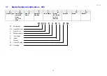
Страница 14: ...r hinging R Right hand L Left hand Style D Designer E Elegance I Inox M Iridium T Tasman Series Brand FP Fisher Paykel Colour of the cabinet and doors WW White cabinet white doors SA Sandstone cabinet...

Страница 15: ...e Capacity of cabinet in Litres 610 610 litres French Doors Designer Handles Ice Water Colour M Iridium X S S Ezkleen Iteration Brand Market RF 610 A D U M 2 FP SG RF Refrigerator 610 Litres Cubic fee...

Страница 16: ...uirements that must be adhered to at all times Specific safety issues are 1 Electrical safety 2 Electrostatic discharge 3 Mixing of foam insulation 4 Vapours while brazing 5 Reclaiming of refrigerant...

Страница 17: ...s will close with the aid of the door closing cams It is also important that the appliance sits solidly on the floor Front and rear rollers are fitted ex factory These are not adjustable Cabinet level...

Страница 18: ...LH or from LH to RH They also include two door B T models single door models and H models in the 635 680 and 790 cabinet widths along with handle colours of white and silver Inox and Elegance models w...

Страница 19: ...duction brazing in the FC POWER CONTROL MODULE Contains the microprocessor that controls all functions of the refrigerator and gathers data from the sensors This module also contains support circuitry...

Страница 20: ...n to another fan which supplies the cold air into the PC compartment The amount of air is controlled electronically by two sensors which in turn regulate through the power control module the speed of...

Страница 21: ...ies the cold air into the PC compartment The amount of air is controlled electronically by two sensors which in turn regulate the speed of both PC and FC fans to maintain selected temperatures in each...

Страница 22: ...R BOTH PC AND FC TURNS OFF TURNS ON TURNS OFF TURNS ON FANS TURN ON DEFROST TIME TARGET IS 18 MINUTES OR SENSOR REACHES 8 O C 2 MINUTES MAXIMUM IS 40 MINUTES 4 MINUTES 30 SECONDS NORMAL RUN WARM UP DE...

Страница 23: ...AN FC FAN TURNS ON TURNS OFF TURNS ON TURNS ON DEFROST TIME TARGET IS 25 MINUTES OR SENSOR REACHES 8 O C MAXIMUM IS 65 MINUTES 4 MINUTES 5 MINUTES 12 8 MINUTES NORMAL RUN DEFROST DRIP TIME BACK TO NOR...

Страница 24: ...ng the filter drier which is mounted vertically in the unit compartment Now the high pressure gas has been condensed the liquid refrigerant flows through the capillary tube entering the evaporator mou...

Страница 25: ...n the centre of the liner A tube then allows the condensate to flow into a water evaporation tray above the compressor 4 7 Filter Drier Diagram 4 7 The filter drier or molecular sieve as the name sugg...

Страница 26: ...sections to locate which section is at fault Always ease the back panel away from the cabinet slightly before pressure testing the internal pipe work This will prevent a pressure build up within the c...

Страница 27: ...321144 27 4 8 1 Condenser Lay Out 635 680 790 T Models CONDENSER WITH TUBE CROSS RAIL BACK PANEL CIRCUIT REMOVED FOR CLARITY ALL BRAZED CONDENSER JOINTS ARE EXTERNAL IN UNIT COMPARTMENT Diagram 4 8 1...

Страница 28: ...1144 28 4 8 2 Condenser Lay Out 635 680 790 900 B Models CONDENSER WITH TUBE CROSS RAIL BACK PANEL CIRCUIT REMOVED FOR CLARITY ALL BRAZED CONDENSER JOINTS ARE EXTERNAL IN UNIT COMPARTMENT Diagram 4 8...

Страница 29: ...riac solid state switching device on the power control module 4 13 Thermal Fuse There are two thermal fuses mounted in the wiring harness of the defrost element having a tripping temperature of 72O C...

Страница 30: ...ier between the FC and PC compartments also allowing return air from the PC to move back to the FC evaporator in T models In both models it houses the PC fan motor In B models it houses also the low a...

Страница 31: ...he ice accumulated on the evaporator The defrost heating element used on the evaporator is of an inconal folded type having both wiring terminations at one end The defrosts are adaptive to the usage a...

Страница 32: ...culation if a defrost has occurred or there were long cycle times T MODEL Diagram 4 19 4 20 PC FC Fans 4 20 1 B Model Fan There are two 12 Volt DC electrically commutated motors ECMs They provide the...

Страница 33: ...aks in the area of the top of the duct T Model PC Fan Fan in Position Diagram 4 20 2 NOTE The same PC fan assembly is supplied as a spare part for both B and T models This part comes with the air shro...

Страница 34: ...To prevent overheating of the lens cover the lamp is turned off after 5 minutes if the door is left open and the module will beep continuously indicating that the door has been left open T models have...

Страница 35: ...e ice tray 5 On ice water models a water tank sensor mounted at the rear of the water tank used to measure the temperature of the water tank Thermistor sensors are used for temperature measurement The...

Страница 36: ...s compartment 2 The temperature can be altered by pressing the TEMPERATURE UP or TEMPERATURE DOWN buttons Fewer LED lights on the thermometer means a cooler temperature 3 To adjust the freezer tempera...

Страница 37: ...porator then to use the fans to efficiently cool the compartments Both fans turn on with the compressor The freezer compartment FC fan is kept at a constant speed while the produce compartment PC fan...

Страница 38: ...f memory device call an E 2 PROM The information on the fridge operation faults and diagnostic information is stored in this memory They include the temperature setting the history of FC PC temperatur...

Страница 39: ...refrigerator compartments The user interface is positioned at the right hand side of the fresh food compartment PC The interface automatically displays the current temperature setting for the PC comp...

Страница 40: ...r potentially ramps up to some higher speed Whenever the refrigerator is plugged in turned on and or after a defrost in the first cooling cycle the control will run the compressor after its initial st...

Страница 41: ...refrigerator there should always be mains voltage 230V or 110V as supplied to the appliance by the household supply in the high voltage harness between the power control module and the VCC module inv...

Страница 42: ...shes Compressor failure Figure 1 Label on the VCC 3 inverter box Figure 2 LED position on the inverter box Code Compressor Status Probable Root Causes Service Action ON No Fault Detected All OK with t...

Страница 43: ...essor is OFF Replace the compressor LED OFF No LED on OFF No Input power signal Inverter damaged Check the input power signal 230 volts If there is no signal Check the input power connection from the...

Страница 44: ...nction With the aid of a multi meter a number of points can be tested on the inverter while it is in a running state To carry out these tests the probes on the meter need to be sharp and have fine poi...

Страница 45: ...to the compressor and refit the compressor cover Step 2 Check the input voltage to the inverter Remove the protective terminal cover from the inverter reconnect the appliance to the power supply and s...

Страница 46: ...he fault to be in the power controller Output Voltage The measurement of an output voltage using a multimeter voltmeter will not give a valid reading in a no load state because once the inverter is un...

Страница 47: ...ntrol module Replace power control module with new part and test Suspect inverter module Replace inverter module with new part and test No No No No Yes Yes Yes Yes Note A damaged compressor could caus...

Страница 48: ...re Ice and Settings Arrow Buttons The ARROW buttons are used to scroll through the settings of each function Lock The LOCK button enables and disables the water dispenser and all the buttons 7 1 Displ...

Страница 49: ...to its coldest temperature set point for a 12 hour period To access use the MENU button to scroll to FREEZER then use the up or down button to get fast freeze To deactivate manually use the MENU butto...

Страница 50: ...ndicates the product is in Key Silent mode To activate or deactivate hold the MENU button for four 4 seconds 7 3 7 Dispenser Lock This mode disables the water dispensing pad and prevents water from be...

Страница 51: ...for 4 seconds Filter Reset Lock Up Reset Hold down for 4 seconds Manually Force Icemaker Harvest Lock Down Up Activates once Hold down for 4 seconds 7 5 Temperature Settings PC Setting 0 0 O C 0 5 O C...

Страница 52: ...late the amount of time taken to do a cycle and then flips After this point it will run normally calculating the amount of time for each batch The rate of production will depend on the temperature of...

Страница 53: ...Tube Heater There is a heater located under the fill tube nozzle to prevent the fill tube from freezing It is connected in series with the low ambient heater 8 6 Pressure Limiting Valve The pressure l...

Страница 54: ...cking Together If the FC door is left open for an extended period or the ice bin is removed and allowed to warm up the customer may find the ice cubes sticking together in the bin to form a large bloc...

Страница 55: ...l stop water flow clear of the refrigerator unit compartment and not in a location where it can be squashed Ensure that all push fit connections are firmly pushed into place The tube should push in 20...

Страница 56: ...the new cartridge Push the cartridge upwards towards the head while rotating it in a clockwise direction to the right when installed in the recommended orientation Reset the filter icon on the display...

Страница 57: ...efrost element assembly in the FC If faulty replace Fault Code 3 Reason The resistance of all the temperature sensors are outside the normal range 45K Ohms Primary Action Check the 6 way RAST connecto...

Страница 58: ...ter is drawing less current than expected Either the heater or wiring is open circuit or the heater is faulty Primary Action Check the wiring and connections at both the heater and the power module Se...

Страница 59: ...sensor Secondary Action Replace the sensor Fault Code 24 Reason The resistance of the ice tray sensor is outside the normal range 45K Ohms Sensor cold Primary Action Check the connections of the senso...

Страница 60: ...on Check the solenoid resistance If not within limits replace the solenoid Check the wiring and connections at the solenoid and the module If OK replace the power control module Fault Code 42 Reason I...

Страница 61: ...on 4 22 10 1 3 Testing Icemaker Motor Testing of the icemaker motor is carried out at the power module NOTE Before any testing is carried out ensure the product has an ice bin in place and the icemake...

Страница 62: ...Checking the tact switch Advancing the motor 10 1 4 Testing Water Valve The water valves are located in the compressor unit compartment Disconnect the refrigerator from the power supply Remove the con...

Страница 63: ...pliance is in diagnostic mode PC Sensor Temperature NOTE 4 0 shown on display indicates the temperature of the PC sensor is 4 0O C 39 2O F Diagram A PC Sensor Temperature FC Sensor Temperature Press t...

Страница 64: ...Sensor Temperature Press the UP button once more PC2 sensor This sensor is attached to the water tank NOTE 5 0 shown indicates the temperature of the PC2 sensor is 5O C 41O F Diagram E PC Sensor 2 Ice...

Страница 65: ...are any further faults with the display board If an icemaker display fault has occurred these will be indicated by fault codes F40 or F41 on the LCD Display NOTE This is fault history and may not nec...

Страница 66: ...ither removed or pushed backwards for the icemaker to complete a full rotation Bin lever in down position When in this position the icemaker will not rotate harvest 10 1 11 Data Download To place the...

Страница 67: ...s the refrigerator is turned on or as soon as the doors are closed the service technician should wait for 20 seconds before opening the door to check the fault code This will allow the refrigerator to...

Страница 68: ...ason The resistance of the PC sensor is outside the normal range 45K Ohms Primary Action Check the sensor connection at the power control module Secondary Action Replace the sensor Fault Code 10 Reaso...

Страница 69: ...an is drawing more current than expected Either the wiring is shorted or the fan is faulty Primary Action Check the PC fan wiring and connections at both the fan and the power control module Secondary...

Страница 70: ...ensor temperature The current FC sensor temperature is displayed in a code form refer Section 10 2 3 2 times Defrost sensor temperature The current defrost sensor temperature is displayed in a code fo...

Страница 71: ...e steps are 1a Press and hold the MODE button a short beep will sound 1b Whilst still holding the MODE button briefly press the TEMPERATURE UP button a short beep will sound This enters diagnostic mod...

Страница 72: ...g it will be heard to stop NOTE If the MODE and TEMPERATURE DOWN buttons are pressed only once the forced defrost will not occur when the compressor cycles off 2 To check if the appliance is in defros...

Страница 73: ...ned There will be no set temperature lights LEDs displayed on the display module The door alarm will be disconnected and will not sound even if the doors were to be left open NOTE When in the special...

Страница 74: ...ezing Door may have been left ajar Check door closing to identify any potential causes gasket sticking door closing hook Freezer compartment too warm Check PC and FC settings Check temperature of FC a...

Страница 75: ...of the icemaker tray Refit the wiring connector Place the harness into the groove on the edge of the body of the icemaker Locate the clips and align the icemaker to the clips With an upward pressure r...

Страница 76: ...Step 2 Two locating pins on the base of the front panel hold the housing at the bottom NOTE The housing cannot be removed as wiring looms prevent its removal Step 3 Disconnect the RAST connectors from...

Страница 77: ...e PC sensor from the PC duct cover Unclip the water reservoir cover from the cabinet liner The reservoir is removed by sliding a flat bladed plastic putty knife or spatula on top of the tank and with...

Страница 78: ...circuit 43 icemaker current low open circuit Checks Test the heater resistance at the power control module terminal The heater is the pink wire plugged into door heater slot at the bottom of power co...

Страница 79: ...before it will come loose Step 3 Pull the heater out of its pocket to expose the pink harness There is surplus harness Step 4 Cut the faulty heater from the harness but make sure to allow sufficient w...

Страница 80: ...es are well clear of the water outlet around the spout Tape the wires against plastic surfaces in the spout recess to ensure they cannot fall into the path of the water This is important to ensure the...

Страница 81: ...cover will allow a screwdriver to be used to remove the hinge cover trim without damaging the hinge cover With a flat bladed screwdriver and using the hinge bracket as a lever gently lever the centre...

Страница 82: ...Fit the harness to the bullet supplied with the replacement door and tape the harness to the bullet NOTE This is required to pull the harness through the conduit Ease the bullet into the conduit and d...

Страница 83: ...ide arm NOTE The tape mark on the bottom of harness guide arm gives the correct amount of wire length under the hinge cover to couple to the edge connector The lay of the harness in relationship to th...

Страница 84: ...p hinge bracket Remove the screw from the door Remove the hose and wiring harness from the guide Turn the guide 90 degrees to the door and lift to remove it from the door Remove the hose from the door...

Страница 85: ...binet From the harness RAST connector measure 300 mm 11 inches and place a mark on the harness The mark on the harness is to be placed in the middle of the guide Push the hose through the guide until...

Страница 86: ...be trimmed on the end to prevent leaks Ensure that the hose is clipped into position correctly Refit the LCD housing ensuring that the wiring harness is firmly in place and is not preventing the hous...

Страница 87: ...econnect the RAST connector Refit the hinge cover NOTE If the original water tube is to be refitted check the end of the tube for any damage and if the tube has small pieces of plastic protruding cut...

Страница 88: ...never any part of the electrical circuit is serviced or disturbed in the course of carrying out service adjustments or procedures it is essential that an insulation and earth continuity test be carrie...

Страница 89: ...partment on the right hand side and held in place by 2 self tapping screws 1 Disconnect the refrigerator from the power supply 2 Remove both the mounting screws and the earth screw on the green yellow...

Страница 90: ...ich is included with the new service module will give instructions on the initialisation of the module 12 5 Freezer Bin Runner and Air Deflector Removal E402B and E372B Models 1 Disconnect the refrige...

Страница 91: ...ng Tab in to release bracket from slide Locking Tab Photo 12 7 12 7 1 Refitting Of The FC Drawer 1 There are two locating tabs on the drawer that are required to be fitted first Refer Photo 12 7 1 Ste...

Страница 92: ...he wiring harness multi plug first into the pocket of the divider partition 8 Using your 2 fingers slip the motor back into the divider partition to fit horizontally NOTE The back of the fan motor fac...

Страница 93: ...FC Sensor Replacement T and B Models 1 Disconnect the refrigerator from the power supply 2 Prise out the fan shroud using a flat blade screwdriver at the bottom of the grill cover 3 Unclip the FC fan...

Страница 94: ...Remove the paper backing off the replacement heater and place the heater 150mm 6 inches from the base of the PC duct cover as shown on left 6 Connect the new LAH to the plug socket that the old one w...

Страница 95: ...apper hinge to the door liner Refer Photo 12 22 3 Second screw located in front of hinge Photo 12 22 3 6 Remove the flapper off the bottom hinge and turn over to expose the bottom of the flapper 7 Sli...

Страница 96: ...321144 96 Photo 12 22 5...

Страница 97: ...F 01T PO 5A 26 20 AWG SYF 41T PO 5A 20 16 AWG There are two sizes of terminals to suit the wire gauges 819607P 819608P Sold as packet of 10 RETAINER 2 WAY 3 WAY Common to both plugs and sockets YLS 02...

Страница 98: ...AY 5 WAY 6 WAY 7234 003 500 450 7234 005 500 450 7234 006 500 450 NOTE 2 873251 881135 873247 NOTE 1 In the part names of these connectors the 02 refers to it being a 2 way connector and the AB01 for...

Страница 99: ...bottom of the evaporator cover and pulling up and forward Diagram 12 24 12 25 Active Smart PC FC Fan Motor Tester Testing a PC or FC fan motor with a multi meter is not possible due to the electronics...

Страница 100: ...321144 100 Diagram 12 25...

Страница 101: ...f ignition inside the appliance in case the appliance should have a gas leak Always purge the system with Dry Nitrogen prior to lighting a gas torch 13 2 Leak Detection There are special leak detector...

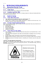
Страница 102: ...0a REFRIGERANT ISOBUTANE The refrigerant contained within the sealed in system is flammable All care must be taken when servicing these products Vent well before brazing Avoid any open flames or ignit...

Страница 103: ...tep 10 Use a bit of masking tape to mark the face of the pressure gauge at the set pressure Record date and time on the tape also Step 11 Check all exposed brazed joints with soap bubbles including th...

Страница 104: ...ystem when the refrigerator is plugged into the power thus causing problems such as a blocked capillary or the compressor not pumping due to oil being slugged in the system To overcome the likelihood...

Страница 105: ...of the ABS liner as heating the heat shrink can cause the liner to be overheated It is also important to keep the thermal fuse in the element circuit away from the heat gun as heat from the heat gun c...

Страница 106: ...nhale any vapour from the liquids b Measure chemicals by weight only and NOT by volume Not essential for small quantities used for filling voids after repair c Avoid contact with skin or clothing d Us...

Страница 107: ...nal condenser firstly recover the refrigerant then disconnect the condenser piping to the back panel Lay the cabinet face down using a protective covering on the floor to prevent any damage to the fro...

Страница 108: ...321144 108 13 11 Embraco Compressor Fitted With External Overload Diagram 13 11...

Страница 109: ...321144 109 13 12 Matsushita Compressor Fitted With External Overload And Run Capacitor Diagram 13 12...

Страница 110: ...sor and connecting to the recovery unit 3 Disconnect the electrical harness leads from the relay and overload Electric s must be returned with the failed compressor 4 Unbraze the compressor suction di...

Страница 111: ...terminal block and harness to relay 4 Check the overload for continuity 5 Test the PTC Relay Remove it from the compressor and using an ohmmeter check the resistance through the PTC itself between M...

Страница 112: ...may be fully or partially blocked Very high head pressure Normally a blockage before the condenser 6 The condenser too hot e g air movement blocked or ambient temperature too high The refrigerator may...

Страница 113: ...5 harness colours Display Blue Sensors PC Brown FC Fan LAH T model Yellow Cross Rail Reed Switch Black Sensors Evap Black PC Fan T model Pink Base Rail Reed Switch Red Sensors FC White Fans LAH B mod...

Страница 114: ...321144 114 14 2 Non Ice Water Models Wiring Diagram...

Страница 115: ...colours Display Blue Sensors PC Brown FC Fan LAH T model Yellow Cross Rail Reed Switch Black Sensors Evap Black PC Fan T model Pink Base Rail Reed Switch Red Sensors FC White Fans LAH B model Orange O...

Страница 116: ...321144 116 14 4 Ice Water Models Wiring Diagram...

Страница 117: ...321144 117 14 5 900 Models Power Control Module Wiring Connections Reciprocating Compressor...

Страница 118: ...321144 118 14 6 900 Models Wiring Diagram Reciprocating Compressor...

Страница 119: ...321144 119 14 7 900 Models Power Control Module Wiring Connections VC Compressor...

Страница 120: ...321144 120 14 8 900 Models Wiring Diagram VC Compressor...

Страница 121: ...321144 121 14 9 B Model Wiring Route Diagram 14 9...

Страница 122: ...321144 122 14 10 T Model Wiring Route Diagram 14 10...

Страница 123: ...polarity Check for broken wires Replace fan Total Compartment Too Cold FC fan not going Check for fault code refer to Sections 10 1 1 or 10 2 1 Check for mechanical obstruction Check for broken wires...

Страница 124: ...Check set temperature Sensor clipped and located in correct position Faulty sensor Check calibration of sensor ice point using interface binary refer to Sections 10 1 5 or 10 2 3 or refer to thermisto...

Страница 125: ...refer to Section 4 3 If no click check power control module If click heard check the defrost heater 230v output at the power control module Sensors Check display for fault codes 0 5 Sensors above or b...

Страница 126: ...re sealing Ice on grill Clear ice off grill and check doors are sealing Fan off mountings Refit Wires touching Tuck wires away from fan blade Capillary touching Shift capillary from fan area making su...

Страница 127: ...y flooded evaporator If not check for leak Fans not working Check for fault code refer to Sections 10 1 1 or 10 2 1 Is there a 12Volt supply PC light working If yes check fan connection s at fan end a...

Страница 128: ...rost circuit continuity Doors sealing Adjust PC fan running If not refer PC Too Warm ALARM ON Defrost heater Check display for any fault code Check defrost element continuity Put cabinet into manual d...

Страница 129: ...lise power control module refer to Section 12 4 1 If raspberry noise made when attempting to initialize check door switches NOISY FAN PC Ice around gasket Replace assembly with new fan kit Wires touch...

Страница 130: ...oo Cold PC Too Warm 16 5 PC Too Cold 16 6 Ice Condensation Forming 16 7 No Light 16 8 Door Switch Not Operating 16 9 Defrost Heater Faults 16 10 Compressor Faults 16 11 Compressor Runs Continuously 16...

Страница 131: ...tlet socket No Yes Has product been initialised Is there 12V DC between the power control module and the display module No Is there power to the power control module Are any LEDs on at the display mod...

Страница 132: ...ir or replace faulty components Replace power control module Is there power to the refrigerator PC light LEDs on Repair fault in house wiring No Is there power to the house power supply Yes Yes No Rep...

Страница 133: ...ilable Refer to Section 16 10 Refer to Sections 10 1 1 and 10 2 1 Repair or replace faulty components Are temperature settings correct Are temperatures of contents of PC FC OK Advise customer temperat...

Страница 134: ...Is Smart Tool download available Refer to Sections 10 1 1 and 10 2 1 Repair or replace faulty components Are temperature settings correct Check door gasket sealing is OK Install components correctly s...

Страница 135: ...of PC frozen Is Smart Tool download available Refer to Sections 10 1 1 and 10 2 1 Repair or replace faulty components Are temperature settings correct Check assembly of all ducts covers Check for blo...

Страница 136: ...lable Repair or replace faulty components Check that drain is not blocked Are the door gaskets sealing correctly Explain to customer that some ice condensation is normal in heavy usage situations Is t...

Страница 137: ...initialised Check is light bulb OK With FC door closed and PC door open press Mode button Replace faulty component Repair Replace power control module Repair replace faulty component Refer to Section...

Страница 138: ...ble a Smart Tool data download will verify door switch failures by very high door open counts V actual openings Replace reed switch Repair Yes No Yes No Does FC door LED switch on off as FC door is op...

Страница 139: ...ir or replace faulty components Advise customer no fault found Check correct operation of defrost heater Check location of defrost sensor Check if door has been left ajar Yes No Repair replace faulty...

Страница 140: ...display module illuminated Is refrigeration taking place With FC door closed and PC door open press Mode button Check for loss of gas leak or blockage Check for correct fitting of sensors Check senso...

Страница 141: ...heck compressor and system for leaks blockages and repair as required Yes No Remove FC cover Is there a full frost pattern on the evaporator Yes No 16 12 Compressor Will Not Run And Is Hot To Touch 16...

Страница 142: ...k temperatures Check compressor and system for leaks blockage and repair as required Yes Yes No No No Remove FC cover Is there a full frost pattern on the evaporator Yes Should the compressor be runni...

Страница 143: ...e Is it correct to specs Replace water valve Turn tap back on again and check water flow from tube Turn tap off Disconnect water tube at water valve Does water come out of tube Replace water valve Tur...

Страница 144: ...test Is the lever detect in place Yes Yes No No Yes Is the Ice tray filling with water Yes Force a harvest and check if tray fills Check FC temperature Has FC reached 8 C No Investigate reasons for FC...

Страница 145: ......
Отзывы: