3 | Installation and assembly
FISCHER Mess- und Regeltechnik GmbH
8 / 28
BA_EN_NK10
3 Installation and assembly
NOTICE! The information in the safety manual must be observed in con-
nection with equipment with functional safety.
3.1 Process connection
The process connection may be realised by authorized and qualified specialized
personnel.
The unit is set ex-works for horizontal installation. Only this installation position
is allowed.
Dangers caused by pressure on the instrument are to be prevented with suit-
able measures.
The flange and/or process connections are designed for a working temperature
of max. 400 °C and a working pressure of max. 20 bar.
CAUTION
The data of the flange used may be lower.
Please check the actual data in the technical data section.
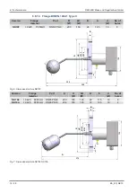
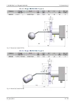
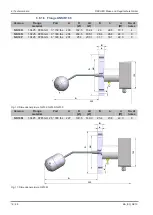
There are a range of flanges and welded hexagon nipples with which the device
can be installed on-site. Take care that the side of the device marked
TOP
faces upwards when being installed.
NOTICE! Please check:
• The swimmer must be able to move freely in the vertical direction!
• Test the switching function using the test button.
3.2 Electrical connections
• By authorized and qualified specialized personnel only.
• When connecting the unit, the national and international electro-technical
regulations must be observed.
• Disconnect the system from the mains, before electrically connecting the
device.
• Install the consumer-adapted fuses.
• Do not connect the connector if strained.
When laying the electrical supply lines, ensure that no short circuit between the
electrical conductors and the surroundings can occur.
A locking and unlocking system as per DIN 4754-3 must be incorporated, if the
device is used as a fill level limiter. This safety system must conform to DIN
50156 / VDDE 0116.
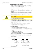
3.2.1 Circuit diagram
1
2
3
Test button
1
2
3
4
5
6
1 Switch
(S1)
2 Switch
(S1 with warn switch S2)
PE
PE
PE
Fig. 2:
Circuit diagram
Содержание NK10 B
Страница 1: ...Operating manual NK10 Fill Level Limiter 09005111 BA_EN_NK10 Rev ST4 E 01 19 09005111 ...
Страница 19: ...FISCHER Mess und Regeltechnik GmbH Attachments 8 BA_EN_NK10 19 28 Fig 13 CE_DE_NK10 part2 ...
Страница 22: ...8 Attachments FISCHER Mess und Regeltechnik GmbH 22 28 BA_EN_NK10 Fig 16 DNVGL_TAA000020S_Page_2 ...
Страница 23: ...FISCHER Mess und Regeltechnik GmbH Attachments 8 BA_EN_NK10 23 28 Fig 17 DNVGL_TAA000020S_Page_3 ...
Страница 27: ...FISCHER Mess und Regeltechnik GmbH Attachments 8 BA_EN_NK10 27 28 Fig 21 SIL_IEC61508_DE_EN 1 Part2 ...

