


11
®
4.
Before tightening the mounting tube squeeze collar, rotate the guide tube, as necessary, to accept
the cooling/combustion air flexible hose connection.
5.
Connect the cooling/combustion air flexible hose to the SureFire™ guide tube.
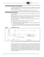
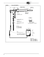
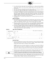
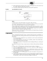
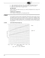
FIGURE 5.
Typical HEI Spark Rod Tip Location
Wiring
Consult the control system wiring diagram for site-specific wiring connections.
The SureFire™ igniter requires ac service to the HEI power unit and AC or DC service to the block
and vent valve solenoid(s) and block valve position switch (if applicable).
Before commissioning the equipment, test all electrical components for proper operation by energiz-
ing the component while it is isolated from the system. Improper operation or failure of a component
to operate requires troubleshooting techniques, such as performing a continuity check, locally ener-
gizing the component, or temporarily bypassing the interlock.
Keep accurate records of all electrical tests. Before proceeding with commissioning, all interlocks
must be restored to operating condition.
COMMISSIONING
Before commissioning the SureFire™ igniter, complete all of the steps listed in the Installation sec-
tion of this manual. Use the following checklist to ensure that the SureFire™ igniter is ready for ini-
tial operation.
•
The fuel and air piping configuration is correct, and dampers, valves, strainers, and instrumenta-
tion are installed properly.
•
The air and gas connections to the guide tube are installed according to the preceding instruc-
tions or the installation drawings (if provided).
•
All electrical components are wired properly and tested, including the HEI power unit and spark
rod assembly.
To commission the SureFire™ igniter, complete the above checklist and then perform the following
steps:
1.
Remove the 1/8" NPT pipe plug near the observation port and connect a manometer.
2.
Place the cooling/combustion air system into service by starting the cooling/combustion air
fan(s) and opening the isolation valves.
3.
Adjust the cooling/combustion air manual valve to approximately 0.5 inch w.c. above furnace
pressure, as measured at the rear flange. Alternately, use an air flow measuring device to mea-
sure and adjust for approximately 12 SCFM flow.
4.
When the 0.5 inch w.c. or 12 SCFM pressure is set, remove the manometer and replace the 1/8"
NPT pipe plug.
5.
Prepare to place the SureFire™ igniter in service by setting the igniter gas header pressure regu-
lator to the pressure required at the igniter gas connection. (Installing a temporary test gauge at
the igniter helps to observe fuel pressure while performing proceeding step.
GAS PILOT
ORIFICE
IGNITER
TUBE
HEI SPARK TIP
BAFFLE
PLATE
GAS TRANSPORT TUBE
GUIDE
POSITIONED EVEN
WITH BAFFLE PLATE
Содержание SureFire 20
Страница 15: ...15 ...