


56
Application, Installation & Commissioning Doc. version 2
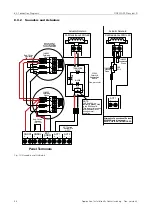
8.3 Connection Diagrams
FIRECLASS Prescient III
8.3.4
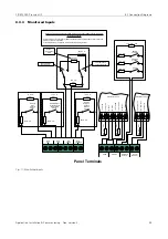
Monitored Outputs
Fig. 12: Monitored Outputs
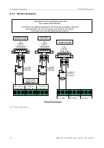
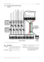
Panel Terminals
C /+
P
O /-
C /+
P
O /-
C /+
P
O /-
C /+
P
O /-
C /+
P
O /-
C /+
P
O /-
GAS REL SIG
FIRE SIG
FAULT SIG
3RD STAGE
2ND STAGE
1ST STAGE
+
-
Relay
Coil current
<=100 mA
Operating Voltage
19V to 30V DC
+
-
+
-
Fault Output,
Normally energised
Gas Released Output,
Normally de -energised
Fire Signal Output
wired same as Gas
Released Output
1
st
Stage Shutdown Output,
Normally de - energised
10k EOL
These Outputs are Reverse - polarity monitored at 5 VDC.
They are Active at 28 VDC (Nominal)
Each Output can be configured independently for Volt-Free contacts by removing the relevant links
on the motherboard. The volt - free contacts are rated at 1 Amp, 30 VDC maximum.
DO NOT SWITCH AC VOLTAGES THROUGH THESE CONTACTS
10k EOL
10k EOL
Relay
Coil current
<=100 mA
Operating Voltage
19V to 30V DC
Relay
Coil current
<= 100 mA
Operating Voltage
19 V to 30 V DC
2 x 1N4002 S
DIODES OR
EQUIVALENT
2 x 1N4002 S
DIODES OR
EQUIVALENT
2 x 1N4002 S
DIODES OR
EQUIVALENT


